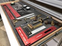
BF/MFT Build

AtomicRyan said:
Got the guide rail by [member=70143]RightAngleDesign[/member] installed and squared... This thing is made really well and handles the long guide rail without issue. I’ll cover it in detail on the next video.

I like that sacrificial strip a lot! My MFT (yet to be finished) top is laminated with Formica Microdot, so I don't want to cut into it. Adding a string like this is a perfect addition!

I tried to look up details about the guide rail, can you share some more info, looks interesting.
 
Yes, more info on the guide rail mount. I did a search and didn’t find anything. I am designing my 8020 MFT bench, on a smaller scale, and am curious about this option. Thanks

Sent from my iPhone using Tapatalk
 
The guide rail pivot is amazing. I 100% endorse it.

Also... I usually make fun of people that use kaizen foam... Now, I can make fun of myself!


Attachments

  • D50FD49B-2B75-4E2B-A58F-D9EBF19D3D43.jpeg
    D50FD49B-2B75-4E2B-A58F-D9EBF19D3D43.jpeg
    412.3 KB · Views: 3,306
AtomicRyan said:
The guide rail pivot is amazing. I 100% endorse it.

Also... I usually make fun of people that use kaizen foam... Now, I can make fun of myself!
Fantastic!  I’m an early adopter of the Right Angle Design system. I use my tables everyday and have the best of both worlds with easy transport and set up combined with shop accuracy. Thanks for sharing your project

Sent from my iPhone using Tapatalk
 
Anyone know if this system works in combination with 8020 profiles? Or can it only be used with the MFT-rails?
 
hdv said:
Anyone know if this system works in combination with 8020 profiles? Or can it only be used with the MFT-rails?
It works with 80/20, I confirmed yesterday before placing an order.

Sent from my iPhone using Tapatalk
 
Sorry. I should have been clearer in my question. Indeed, I meant the jig by RightAngleDesign.

Thanks for confirming the compatibility [member=67145]Dusty.Tools[/member]! I think I've found my Christmas present. [embarassed]
 
[member=63929]AtomicRyan[/member]

Great Idea. I did something similar a while ago except ILO HDPE I used scrap hardwood.

What I didnt do but should of (lets call yer sacrificial strip a vertical Strip). I would of made on horizontal to. Very convienent for cutting length wise.
 
AtomicRyan, in your video where you discuss coating your top with the 50/50 mixture of mineral spirits and wipe on poly, did you apply it to the bore of your holes?  And if so, did it purely soak it in or did it affect the ability to insert dogs?

I got my baby 33”x57” MDF top drilled up the other day using my Parf System, and just purchased the stuff to finish it today. Still need to sand it down before applying.

Thanks
 
08G8V8 said:
AtomicRyan, in your video where you discuss coating your top with the 50/50 mixture of mineral spirits and wipe on poly, did you apply it to the bore of your holes?  And if so, did it purely soak it in or did it affect the ability to insert dogs?

I got my baby 33”x57” MDF top drilled up the other day using my Parf System, and just purchased the stuff to finish it today. Still need to sand it down before applying.

Thanks

It’s so thin that the edge grain of the dog holes just soaks it up. I’ve done tons of coats and it hasn’t messed with dog fit at all.

[member=10147]jobsworth[/member] Great idea.
 
As an aside - Does anyone know if the placement of the first row of holes is important?

A Festool MFT has them placed 70mm edge to center for the first row. Then all other rows are 96mm. With the last also being 70mm.

When designing a top, is it important to stick to the 70mm + (96mm x #rows\columns) + 70mm sizing?

The implication is a top needs to be based on the following dimensions:

428.0mm (4 holes)
524.0mm (5 holes)
620.0mm (etc.)
716.0mm
812.0mm
908.0mm
1,004.0mm
1,100.0mm
1,196.0mm
1,292.0mm
1,388.0mm
1,484.0mm
1,580.0mm
1,676.0mm

Cheers

Ben
 
I would think their placement is based on linking 2 MFT/3’s together and having the last row of one table and the first row of the second being at the same 96mm spacing.

Sent from my iPhone using Tapatalk
 
08G8V8 said:
I would think their placement is based on linking 2 MFT/3’s together and having the last row of one table and the first row of the second being at the same 96mm spacing.
There'll be one virtual (=not existing) row of holes in the seam between the two tables.
 
I guess I should have said to maintain the multiple of 96mm spacing, or 32mm.  I’m not positive this is true, but would assume it is.

I am making a MfT table from 8020 material, which I wanted to be 3’ x 5’.  I made my top this past week and went 8 rows wide x 15 rows lengthwise. I also wanted to have offset rows along the perimeter to add a fence and dogs to position the guide rails to allow wider cross cuts. I am thinking of adding a foldable wing on one side and will need to figure out how to maintain pattern spacing if I decide to add holes to the wing. The other end of the table will be a router table. I am running an offset row of holes directly down the center for the Incra LS Positioner which will use for the router table fence, and for use with the tracksaw.

But now I am looking at the RightAngleDesign guide rail attachment instead of the offset dogs for rail position.
 
Back
Top