Broken capacitor CTL 26 E AC

poeterdebier

Member
Joined
Aug 24, 2020
Messages
5
Hello Guys,

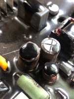
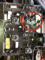
I have two broken capacitors broken inside the electronic part of my CTL 26. So instead of buying a new electronic for about €130,- I will first try to replace the capacitors. Because of the black putty, I could not read the correct data from the capacitors. I think they are:

400 V and 4.7 uF. These are the only values that are compatible with the size (diameter and length) when looking up the specs from Samwha.

Now my question is: can somebody confirm these specs (4.7 uF and 400 V)? I just want to make sure before I put in capacitors with the wrong rating.

Thanks in advance,

regards Piet


Attachments

  • IMG_4193.jpg
    IMG_4193.jpg
    100.9 KB · Views: 1,558
  • IMG_41942.jpg
    IMG_41942.jpg
    108.2 KB · Views: 2,690
I'm not sure you will have much luck removing the conformal coat to remove them, unless you have some experience in removing the stuff.  Generally if you find something that remove it, it removes everything with it.
 
He, thanks for the reply. I was indeed worried about this but with a hot soldering tip, it was actually pretty easy. It did not even get sticky but came off as dry powdery stuff. I attached a picture after removal. Did a decent job if I say so myself. Maybe need some additional cleaning before soldering the new ones. Afterwards I was ablte to pull them out with a tweezer. The legs remained though, I had to desolder them separately.

gr Piet

 
Solder wicking braid works great for cleaning plated holes in PCBs.

Not sure where you are with electronics, besides woodworking, one of my other hobbies is rebuilding vintage audio gear and I’ve  done a fair bit of mucking about inside expensive, high voltage amps.

A couple things to be aware of (just in case you are venturing into new territory)
Most electrolytic capacitors can be had in a variety of can sizes in any given value and outside dimensions will not be a reliable way to identify.  Usually value is printed on wrapper and you hopefully can clean it up well enough to read it. Ideally, getting a schematic would be best.

Mouser and DigiKey are both great suppliers with huge selections.  Be aware that lead spacing is not standardized and you should look for correct spacing to match your PCB

Last, electrolytic caps are polar, meaning there is a positive and negative lead, replacements will need to be installed in correct orientation.
 
Thanks for the reply,

I play around with electronics but an expert I am not. Google is my friend right! Anyway, I was able to identify the capacitors brand as "Samwha". 

Most electrolytic capacitors can be had in a variety of can sizes in any given value and outside dimensions will not be a reliable way to identify.

I got the specifications of Aluminum electrolytic capacitors for this particular brand from the manufacturer site. This also mentions dimensions. See attachment.

Usually value is printed on wrapper and you hopefully can clean it up well enough to read it.

The wrapper was in bad shape though (partly because of me prying it loose from the board and partly because of the putty. The following things however I was able to identify:

Type of capacitor: "RD"
Dimensions: roughly 10x13 (d x L)

Voltage line:

* 1st wrapper: a "4"
* 2nd wrapper: "00 V"

So that must be 400 V right!

The line below the voltage ending with uF:

* 1st wrapper: a "4"
* 2nd wrapper: a "uF"

So a uF something with "4" at 400 V with dimensions around 10x13mm. This can only be a 4.7uF@400V as per specs attached.

Ideally, getting a schematic would be best.

Totally agree. Maybe somebody here on the forum is in possession of said schematics?! I did not ask, but I doubt Festool would provide me with a schematic if I would.

Will try to get me some of this solder wick! Thanks for the tips and advice so far.

gr Piet
 

Attachments

Get the wicking braid with flux imbedded or have electronics flux (not plumbing type!) on hand to add to non fluxed type braid.

How old is the unit?  Caps should easily last 10+ years under normal loads and you may do well to examine board for other issues that caused cap to fail.

All things equal, capacitor housing size grows with voltage rating and capacitance. It’s possible (maybe not likely, but possible) that you have one lower voltage/higher capacitance cap and a higher voltage/lower capacitance cap in your pair and festool sought out identical sizes for manufacturing considerations. 

Sometimes the component value is printed on the PCB so you could gently scrape a bit there to see. Be careful to not cut any PCB traces in case the board is single layer (doubtful) with exposed traces.
 
The unit is about 2 years old. Used it on board of a heavy lift vessel. Bought it with the idea that you can take the whole unit using one hand thus having a hand for your self when going down the stairs. The CTL mini is maybe better suited for this.

Unfortunately, we discovered that the vacuum cleaners are not heavy duty enough (who cares if it breaks down if you are not the on paying for it right!). You could say they are more for people who care about their equipment.

Probably end up buying this Karcher vacuums again (dont ban me  [tongue]). You need 3 people to move them but they are pretty indestructible.

gr Piet
 
[member=73775]poeterdebier[/member] - Are you not in a part of the world where Festool offers its 3-year warranty?
 
TinyShop said:
[member=73775]poeterdebier[/member] - Are you not in a part of the world where Festool offers its 3-year warranty?

Now that he has torn into the board I would say no, but before that I would think so. My expierence working for large contractors is they don't usually register tools like this (
 
Registration is not neccessary as long as the date of manufacture is less than 3 years ago. IOW as long as three years have not elapsed from the date of manufacture printed on the motor tag, the warranty is still in effect. Also, I posed the question - in response to the OP stating that the tool is "about two year old" - as a sort of public service announcement to remind owners to not forget to take advantage of the warranty coverage.
 
I got the CTL through the company. It was broken so it would have been thrown away. I was assuming (never assume  [blink]) that warranty was not an option for me.

The worst-case scenario is to buy a new electronic for around €120,-. A Bargain if you think a new vac costs €750,-.

But to be fair maybe I should have asked Festool before removing things from the board  [tongue]

gr Piet
 
Hi Piet,

I have the same issue with my CTL26. Exact same electronic board as yours. How did the repair go with the capacitors? Was it ok to solder, and did you figure out the polarity?

Regards,
Phil
 
Hi Phil. My CTL 26 smoked and I had hardly used it. I have just taken it apart and managed to remove some of the mask and remove the caps enough to retain the legs from the old caps.
They are 400 volt 4.7 uf. I have measured the board and I don’t get a short, this tells me the caps are one issue. I’m intending to solder in from the top of the board as I can’t justify paying £200 when the blown components amount to pence.
I’ll let you know how it goes.
 
StuMutch said:
Hi Phil. My CTL 26 smoked and I had hardly used it. I have just taken it apart and managed to remove some of the mask and remove the caps enough to retain the legs from the old caps.
They are 400 volt 4.7 uf. I have measured the board and I don’t get a short, this tells me the caps are one issue. I’m intending to solder in from the top of the board as I can’t justify paying £200 when the blown components amount to pence.
I’ll let you know how it goes.

If it makes it easier you could solder IC pins in and then solder the new caps legs to them. With electrolytics they're more prone to going open circuit due to drying out/leaking, not so much short circuit. Heat does affect them badly, so get good heat rated replacements.
 
Back
Top