Building My Own Large MFT-- Input regarding Guide Rails.

JimReed

Member
Joined
Mar 29, 2012
Messages
18
I am biting the bullet to build my own 4'X8' MFT and I have read every FOG thread I can find on this topic.  I am also going to combine some of the features of the Paulk bench.  One thing I definitely want to include is some sort of Guide Rail around the entire perimeter of the bench.  If I could buy the 2M Festool guiderails that apparently are NAINA, I would go that route but since I can't, I am exploring other options and looking for input.

I have considered 80/20 profiles, the LV 5/16 T-track,  the WoodPecker DP track (nice double track http://www.woodpeck.com/dptrack.html) and the Incra T-track, but I don't have any strong front runner choice.  I like the idea of having a double track as I can envision some applications where it might be nice to have the option of using a second track.  My plan is to flush mount the track into the apron of the MFT.

I would love input from anyone who has built their own MFT w guiderails.

Thanks, Jim
 
Hi Jim,

I built my own large MFT (I documented the workbench here a little over a year ago, I called it an "MFT-XL".  It is 36" X 84").  I have not added guide guide rails yet, but want to do so.  I also wanted a vise, and tried the Lee Valley pipe clamp vise as a test, but decided it was not suited to my needs.  I have not added an apron around mine, but have the wood to do so.  Like you, I am just not sure how I want to proceed on guide rails.  I'll keep you posted and will be curious what you come up with, if before me.

I retired a year ago, and started in on some home remodeling.  My wife just retired, so I think with her at home, the remodeling emphasis will get elevated, and my other shop projects will take a back seat to the remodeling.  [wink]

I have bought a bunch of Lee Valley Parf Dogs, and starting to use my workbench for things other than track saw and clamping.  I turn pens, and made a base for my arbor press that has holes in it to drop tall Parf Dogs thru, to anchor to the bench.  Easy on, and easy off.  I keep a large sheet of really thin (a few mm) veneered MDF as a top protector, and when I want a smooth surface to work on, and keep the holes covered.  My workbench is also the outfeed for my table saw, which still gets use for ripping hardwoods.  The track saw for me is mostly used for breaking down sheet goods.

I got interested in track saws watching the Paulk videos over a year ago.  I decided I did not want a portable bench, so I built mine for permanent placement in my basement shop.  I still would like to build a Paulk-style workbench, for use in doing initial sheet good breakdown in the garage.

I'll be anxious to see your progress.

 
Jim,

I would suggest whatever track you go with, try to go with one that provides better support in keeping the track better secured, such as the Woodpecker double sided track you mentioned.  When I build my bench I will be using something of that design, as you want something that anchors better to your workbench and won't pull out under forces.  Not sure but also check out the Kreg tracks.  I think you are on the correct path wrt track design.

Keep us posted as you build.  Many here like to see progress photos!!!

Gary
 
The main uses of the T-Slot appear to me to be:
1. To engage the ends of a guide rail over the table like the MFT/3 does either using brackets like the MFT, or using extensions with dog holes for use with something like Qwas Rail Dogs http://qwasproducts.com/RailDogs.html
2. To accept clamps like the Festool Screw-Clamp or Quick-Clamp for use in clamping boards or sheets of material vertically to the side of the workbench to work on their edges. This use is similar to what a vise would have done on a traditional workbench.
3. To provide a fixing point for a temporary fence, a stop, or some other hardware on the edge of the table.
None of those uses would put much load on the T-slots, so they could be fairly light weight, but if you want to use Festool accessories, it would require that the slots be generically the 5/16” variety rather than the ¼” variety in order to fit them, if that’s your intent. That puts some of the T-slot suppliers, like Woodpeckers and Kreg out of the picture.

And it seems to me that you’d only need one T-slot, not two, on the side of the table, and none on the top. The 80/20 rail used by Qwas on his MFT table is overkill in terms of T-slots, but it provides a strong perimeter structural support for the thin perforated mdf table top.

I think you could do the same thing with 8/4 wood on edge with either an aluminum t-slot recessed into it, or a t-slot routed into it with a router bit like Rockler’s #26099: http://www.rockler.com/rockler-t-slot-cutter-router-bit. I would think that in a dense hardwood like maple, a routed T-slot would perform well for the stresses it would incur, be less expensive than any aluminum track, and it would look good too.

I’m thinking that at least on one side of the workbench I would align the legs of the table with the edge above and run T-slots to the bottoms of the legs, which I intend to mount on casters. That would leave a gap big enough to slip the Festool Screw-Clamps into the slot from the bottom to support the weight of boards or sheets under them.

Any comments?
 
Tom,

I believe routing t tracks directly into the rails is high risk. If they do blow out you're down a bench not a rather inexpensive length of aluminum.
 
My thought was that the perimeter rails would be milled separately and then attached to the rest of the table. I think one could adjust the design to guard against blowouts, but honestly, I’m only speculating; I’d want to make some tests first. Here’s the sequence:
• If the slots were done using a router table, starting with a ¼” slot and following with the t-slot bit using a piece longer than needed, so an end could be lopped off if it were blown out. There’s a video of the router bit being used that way on YouTube:
• If the rails corners were mitered, rather than butted at the corners, and the slots were opened up by hand after the mitered rails were assembled or the outside of the mitered corner were then chamfered vertically to open the ends of the slots, that would also help protect against the chance of blowout experienced by Sean KS :
Sean KS said:
In the third image I originally posted you see that the dado for the t track turns onto the end grain. For the mock up joint I turned the piece vertically on the router table to make this cut. For the actual project this dado is on the end of a 7' work piece, so I cannot turn in upright on the router. I tried on a practice piece to make the cut with a hollow chisel mortiser, but even though it was well backed it blew out in fantastic fashion. My second attempt was making the cut with a razor saw and chisels. I got the dado I was looking for and proved that the method works.
My problem is that I don’t particularly like the look of the t-slot tracks dadoed into the side of the wood, and it’s almost as difficult to do a dado for the track as a t-slot relative to blowouts. I’d be willing to take some additional risk to get it right. One could avoid that issue by going with the 80/20 rails and forgetting wood for the rails.
 
Great topic and hopefully enough ideas and experiences will be shared so others who want the 2 meter rails can find a workaround that they are comfortable with for their shops.

guyswoodshop built a MFT style Table Saw extension where he got creative with shop made rail profiles.

http://festoolownersgroup.com/festool-jigs-tool-enhancements/custom-mfttable-saw-extension-table/msg267112/#msg267112

2/3rds down the post he includes a drawing and a close up photo of his rails. Guy's input would be helpful since he's been using the table for a while now (I'd bet that he would not build in 3 tracks per rail if he were to make a new one).

On Ron Paulk's design there are no tracks and there is no metal in the bench other than screws. Yet he does have an efficient way to clamp vertically to the bench sides. If you are eliminating the Festool fence and miter attachment and just using the dog holes for aligning the track/saw, that simplifies the requirements for the rails. 

 
I'm in the process of building a table right now 3' x 6', less two inches in each dimension because all-thread comes in exactly 3' and 6' lengths around here and I wanted leave some room for learning mistakes and I wanted to trim the all-thread flush. No stretchers at ankle level so that I can wheel my Systainer dollies under the table.

Height is set up so it can double as an infeed table for my saw. The original plan called for a taller table, but I made a mistake and decided to turn it into a virtue. ;)

There isn't much of note about the base. Stretchers are 2x8, which left me enough room for a 3/8" track for the all-thread plus two 10x50mm dominos at each leg-to-stretcher connection. I'm going to have to plane about 1/8" off the bottom edges of the stretchers in order for the dollies to fit when loaded to desired height. The framing is divided approximately in thirds lengthwise; two internal stretchers are present so that the 3/4" MDF top won't sag. The whole thing can easily be taken apart, and it's slotted for Rockler Table Top Fasteners (part 34215) so the top can be replaced at need.

Incidentally, there are people out there using ridiculous choices of lumber on their tables. Run the load calculations before you decide you need a 2x12. Mine seems to be light construction by bench standards, but it can handle several thousand pounds of load. I don't really feel like I need more than that, though if I'd gone to 8 feet I'd have stuck extra legs in the middle to prevent deflection in the longer stretchers.

[Bad method for cutting top holes removed, lest somebody actually try it. Easy way described below.]

 
What are doing (going to do) at the perimeter of the mdf table top, and how do the legs connect to it??
 
Jim,

I built an MFT/Paulk/JackBench hybrid about a year or so ago. Attached are a couple of pics. I have more if you are interested. I recently added a Moxon Vise that I mounted in a wood frame and hooks into the 20mm holes on the MFT top.

Jack
 

Attachments

  • 2013-11-23 12.52.20 resized 35%.jpg
    2013-11-23 12.52.20 resized 35%.jpg
    347.2 KB · Views: 39,855
  • 2013-11-23 12.53.23 resized 20%.jpg
    2013-11-23 12.53.23 resized 20%.jpg
    134 KB · Views: 6,004
Tom:

Funny you should ask. That was the cause of several re-works of the base. My first attempt involved routing a 3/4" x 3/4" deep lip in the 2x8. My thought was that this would simultaneously provide a "seat" for the MDF and also provide a lip around it that would protect the edges of the MDF. This is my first woodworking table, and I outsmarted myself. Assuming straight lumber and more experience I might have gotten away with it. As it was, I should have stuck with the KISS principle.

The current frame (I'll put up a photo tomorrow) doesn't attempt anything so fancy, and I consider it a sacrificial implementation. I'll either let the MDF top wear, or I'll attach a "cladding" piece of 1x?? to the existing sides to implement a frame around the MDF. If I do, I won't worry about making it pretty, since the whole table is throwaway.

It's a truism that you have to have a table to build a table. It surely helps to have a work surface, but it's as much a function of tools-on-hand as anything. When I started, I didn't have a drill press or a planer. The drill press is waiting to go on the (first) table, and I'll be purchasing a planer as soon as I clean up the present mess in my garage. Given straight wood I can build from a design and measurement, but that's hard to do when you are using un-planed wood from Home Depot or your local lumber shop.

Could be I'm kidding myself, and more care might have gotten the job done. All I know is that I discarded two frames with the lip design before I decided (a) to keep it simple, and (b) to use the domino, and then everything worked out. It's tricky to do a metal dowel/peg design accurately without a drill press. So like I say, I may have deluded myself, but it's a learning process, and the next one will be better.

To put this in context, most of what I have built to this point is model railroad benchwork, which is mostly a rough carpentry problem. I'm shifting to more serious attempts, but don't yet have the experience to know what I do and don't know.
 
Tom:

I want to qualify my level of competency, so that you (and others) can evaluate my post here. I'm a hobiest. I've got enough training on electrical to be competent. Concerning wood, I've got enough understanding to know what I want to accomplish and what is feasible without necessarily having the tools or the experience to implement what I have in mind. Getting there, but it's a process.  :) Context: I'm teetering on 50, with a background in critical systems software, and enjoying a hobby where screwups are measured in dollars rather than lives lost. The piper is definitely easier to pay, but I remain inclined to expect perfection.

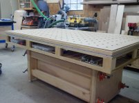
I'm returning to wood construction seriously after a long hiatus, having never really cemented basic skills. My current table frame is the third attempt. The original design called for all-thread and metal pegs - I'm sure you've seen similar starter work table designs. The grooves for the all-thread are simple to anyone who uses a router regularly, but (until recently) I haven't used a router often enough to remember the obvious guidelines. In the course of the current project I have re-acquired a bunch of skills I used to know but had not retained. The third set is near-perfect. The first and second not so much. On the first attempt I messed up the all-thread grooves hopelessly. On the second I re-discovered how hard it is to position holes repeatably without a drill press. On the third I used the Festool Domino. I can't say that this improved my skills any. I can say that the Domino is more repeatable in the hands of a relative novice than a lot of other tools are. Taken overall, I'd say that Festool dust extraction was a significant improvement over my Bosch router table. That's an especially significant improvement for a novice, because visual confirmation is all I have. :)

From the perspective of a novice I'd say that the Domino has been the most game-changing Festool device. I have a circular saw, I know how to measure, and I have a straight-edge. The track saw is more repeatable, but it isn't world-changing when you are trying to cut four stretchers. Similarly, I have a good Bosch router. The OF-1400 standing alone is definitely not an improvement (in fact, it's a downgrade), but combining it with the track and the dust extraction is a qualitative improvement. In both cases I've purchased the corresponding Festool device, and I mostly anticipate selling off the predecessors, but the fundamental benefit wasn't immediately obvious to me as a novice. I'm trained as a systems engineer, and I do appreciate systems engineering, and I can see the advances that Festool has done. But there's a different between "this is better" and "this is qualitatively improved."

For me, the Domino stands out as filling a previously un-filled niche (for the novice), and offers repeatability that the novice cannot otherwise achieve. I'm sure that each customer has their own story for what the turning point was. That was mine. I unpacked the Domino, spent 20 minutes on the manual and on-line how-to's, and then did 96 mortises in 32 minutes. Ignoring one where my hands drifted through user stupidity, the rest were within 1mm of intended location. That seems pretty good for 96 mortises within 62 minutes out of the box. For me, that's game changing. The secret of Festool isn't the precision. It's the repeatability. The two are related, but not the same.

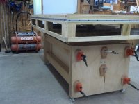
My original design called for the MDF lip and metal dowels/pegs to connect stretchers with legs. The lip was me modifying the pre-existing design in a way that exceeded my experience. I think I could do it now, but at the time it fell under the heading of "make a well-intentioned change so you know it's yours." The pegs are flatly unrealistic unless you have (a) a drill press, or (b) some form of drill guide (Gator or friends). Most importantly, both pegs and teñons fail if you don't have square legs.

About square legs...

I made an early decision that 2x2's were inadequate for an initial work table. This was a mistake. They are inadequate, but 4x4s in the U.S. involve a different grade of lumber that is not dimensionally accurate. You can't reduce a 3.5"x3.5" post with a 10" table saw without a planer (cut depth insufficient). The TS-55 cut depth isn't adequate either for that particular leg. Maybe there was another (better) option that I failed to consider. The point is that I ran into a compound problem: (a) given the tools on-hand I could not cut down a 4x4 and keep it square, and (b) lacking square leg posts a whole bunch of things go wrong when you go to connect stretchers. I suppose the best way to summarize this issue is: when you lack the tools/capacity to square your lumber, it's important to buy lumber that is already square. In my local area, 4"x4" lumber is neither square nor dimensionally accurate, so if you can't square it yourself you're fighting city hall.

This being my third attempt, and having re-acquired some skills, I can see in retrospect why the various web designs were "easy". The thing is: they rely on skills that a novice doesn't actually have. In my case, I compounded the problem by taking what I read and re-designing to avoid ankle-level stretchers. I'm not sure whether that exceeded my initial implementation skills or whether any of the designs would have done so. What I would say in retrospect is that the key to repeatability is fool-proofness, and very few sites seem to talk about that out loud.

Let me bring this to an orderly close. I'm suffering from novice issues coupled with new tools. In retrospect, I'd encourage a qualitatively different approach for new builders. I'm half tempted to start a woodworking blog before I forget. Give where I am now, having learned from that experience, I'm on the other end. I'm resisting changes in the interest of having a table so that I can move forward. All things considered, my investment in tools dwarfs my investment in wood. On the whole, the cost of re-starting the table from scratch in hindsigh is noise.

I suppose what I'm trying to say is this: Whatever table you initially build, it will be obsoleted by experience and you will likely rebuild it. You won't know what you want, and you surely won't have Richard Parfitt's experience. My suggestion is to take this as a given. Build a poor table that works, then build a table to last. With luck, you'll find that the top gets preserved and the frame gets re-done.

I'm a decent document author, and I'd actually like to capture my novice experience in an article/blog entry somewhere. If someone might suggest a vehicle for that, I'd be very greatful.

- Jonathan
 
An addendum to my last two posts...

Most of the "off the shelf" woodworking table designs involve stretchers at ankle level. Lots of reasons for that, and nothing wrong with them, but I wanted to be able to store my Festool Systainers under my table, which meant I couldn't use ankle-level stretchers. So far so good. Conceptually the ankle-level stretchers can be moved up. At some point moving them up makes it harder for your table to be square in the Z (floor-to-table-top) axis.

There isn't a right answer to this in principle. The further you move the ankle stretchers upwards on the legs, the more you are relying on the squareness of your table/mitre saw.

In my case, I knew that my table saw was square within reason, and I decided that separating the ankle stretchers from the table top stretchers by six inches would be enough to minimize my leg squareness. Wonder of wonders, this let me merge the ankle stretcher and the below-top stretcher into a single a 2"x8" stretcher. So long as your table/mitre saw is properly squared, that should be more than enough to square your table legs within reason. Structurally speaking, its enough to park your car on your table, but don't try it. You'll discover that the cement pour in your garage is the weakest factor.

As I've said, I need to post a progressive blog entry on this whole evolution. Hopefully my comments are now accessible to search engines.
 
Tom:

Sorry. Just realized I hadn't answered the "legs" part of your question.

My legs started as US 4"x4". Which is really 3.5"x3.5". Hypothetically. Except that 4x4 in the U.S. is generally decking-grade pressure-treated lumber, and dimensions are a purely hypothetical consideration. You can trim them down, but maintaining square with a TS-55 is impractical because the TS-55 cut depth is inadequate for trimming 4x4" lumber. The TS-75 is feasible if you are prepared to trim down to 2.5" nominal. None of these work if you don't have the capacity to render opposing faces of a 4x4" square, which requires a planer.

Which, speaking frankly, is the next thing on my list.
 
Claimdude said:
Jim,

I built an MFT/Paulk/JackBench hybrid about a year or so ago. Attached are a couple of pics. I have more if you are interested. I recently added a Moxon Vise that I mounted in a wood frame and hooks into the 20mm holes on the MFT top.

Jack

Jack,
That's one massive looking bench.  Interesting construction.  Are those pipe clamps holding the stretchers to the ends?

Mike A.
 
Mike  - That is a height adjustable bench. The clamps allow the base to loosen up to be raised then clamped back down to hold the height and become rigid again.

Here's a link to what appears is the inspiration for this build:

http://www.jack-bench.com/
 
Mike,

You are correct that the pipe clamps hold the stretchers in place and they also lock the lower assembly. The table is at its lowest height in the photos and will raise to 42" from top surface to the floor. If you have never seen the JackBench you can go to JackBench.com and look it over to get more detail. The torsion box base of my MFT top was inspired by Paulk. The perimeter has 1/4" aluminum track for clamping on the sides.

Jack

mike_aa said:
Claimdude said:
Jim,

I built an MFT/Paulk/JackBench hybrid about a year or so ago. Attached are a couple of pics. I have more if you are interested. I recently added a Moxon Vise that I mounted in a wood frame and hooks into the 20mm holes on the MFT top.

Jack

Jack,
That's one massive looking bench.  Interesting construction.  Are those pipe clamps holding the stretchers to the ends?

Mike A.
 
Jack:

That looks like really nice work. When (if?) I get around to replacing my current one, I'll probably do a top similar to yours. I'd originally planned to have drawers for tools on mine, but ended up concluding that as a beginner I'd be better off building a separate drawer cabinet that fit under the table. KISS and all that.

The only thing about that design that concerns me is the protrusions at the ends. I'd be deathly afraid of whacking them with a leg. More a matter of personal taste than anything, I suppose.

- Jonathan
 
Thank you for the kind comments Jonathan. The protrusion are only a concern when I am sitting on my mechanic stool working. Otherwise, the top extends far enough that they are never a concern when standing. You could make the top about 6" longer adding 3" additional overhang on each end and eliminate the problem all together. The bench weighs about 5 or 6 hundred pounds and is solid as a rock when the clamps are tight. Loosen the clamps and use a drill with  5/8" socket on it and either raise the table or lower the wheels and move the bench around. Once moved simply raise the wheels back up and lock the clamps and you are back in business. It took me a little less than a year to build (I am a hobbiest and travel for work a good bit) and cost roughly $1000 for materials.

Jack

shap said:
Jack:

That looks like really nice work. When (if?) I get around to replacing my current one, I'll probably do a top similar to yours. I'd originally planned to have drawers for tools on mine, but ended up concluding that as a beginner I'd be better off building a separate drawer cabinet that fit under the table. KISS and all that.

The only thing about that design that concerns me is the protrusions at the ends. I'd be deathly afraid of whacking them with a leg. More a matter of personal taste than anything, I suppose.

- Jonathan
 
The method I eventually used for setting the holes is dead simple, but it relies on having a gentle touch with a table saw. I'm re-stating some of the problem I faced here, and then I'm going to go back and edit my post above to remove the bad method before some unsuspecting soul tries to follow it.

I used the LR32 set to do the holes, but I had a problem to conquer. I have a roughly 3' x 6' table, but only the 1400mm LR32 rail. I don't have any use for the longer LR32 rail, and I'm surely not eager to spend $300 for a one-time use. The rail I have will span the 3' length just fine, but not the 6' length. I also had to cut the MDF down to get it into my car, so I don't have a lot of overhang to waste. Here's what I did:

First, I cleaned up the MDF by trimming off the damage. I figured how how many holes I wanted to do in the 3' direction and derived the inset of the hole centers from the long (6') edge to be 95.5mm. That is: the gap from the long edge to the closest hole center is 95.5mm. I rounded up, and set the edge guides for 96mm - I caught a break there, as you'll see below. I similarly figured out how many holes in the 6' direction and arrived at an inset on the short (3') edge of 114.5mm. I rounded that up to the next inset that the end stop can handle, which turns out to be 128mm; I'll trim that edge later.

I ran as many holes as I could along one of the long edges, stopping when I ran out of rail. These holes are correctly positioned for the final piece; they won't be getting trimmed off. Leaving the edge guides at the same setting, I shifted the rail down the table and used the router bit as an over-glorified alignment peg so that I could finish the row of holes. If you leave a bit of overlap between the old holes and the new, you can check that the bit fits in two places to ensure that you have correct alignment in two dimensions. And hey! You can use the existing holes to bench-clamp the rail.

I then did the same on the opposite long edge, but this time I put the holes as close to the edge as the MDF would allow. This second row of holes is in waste material. It's parallel to the first row, but it isn't any sort of multiple of 96mm away from the first row. Now to fill in the holes in the middle...

I re-positioned the LR32 rail to run a line of holes along the 3' dimension and put the router and guide on. The end stop can be set for 32mm, which certainly helps process of lining the rail up, but it isn't critical. Now here's the fun part...

I measured my flat-sided dogs and found that they are 19mm and change. On these particular dogs the flat side lines up with the perimeter of the dog shaft. I'll be pushing them to one side of the hole, so that flat side will end up 9mm or so off of the hole center. The rail is 185mm. The LR32 plate puts the center point of the router 25mm off the rail, so that's 185mm+25mm+9mm = 219mm, which means that if I can manage to make a 69mm piece of spacer board I can index new holes off of the old ones. There's actually more slop in my dogs than that 9mm suggests; in the end my spacer ended up at 70.5mm. It took me two tries to get it right. In the end, though, I was able to stick the spacer between the rail and the dogs, snug everything by hand, place the router and guide plate on the rail, and re-insert the bit into the pre-existing holes on both edges. Note here that you want to do the keeper hole first, because at that one you want the router to actually be at a stop. In my case that was easy, because the inset happened to be 96mm which is a distance the edge guide can mark. One way to make this easier is to "round up" your edge distance to something the edge guide can handle directly, and trim off the extra later.

With all this done, the rail is now aligned with the row in both dimensions, and you can proceed to do that row of holes.

Finally, I trim off the extra overhang on all sides and my top is done.

This is loads simpler than the method I described earlier, which I've now deleted lest some poor soul mistakenly tries it. :) The only tricky part is making the spacer, because you'll end up shaving it down half a millimeter at a time as you find the right size to fit your dogs.
 
Back
Top