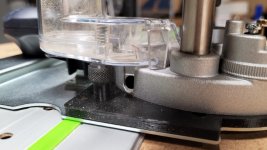
I found a nice knurled M6 knob on Thingiverse and printed a pair of them this morning. They are not very big but still took 47 minutes to print because of the print settings required to get quality threads this size. They came out very nice and fit just fine.
Well learned a lot this morning. Translation = FAILED BIG TIME !
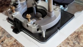
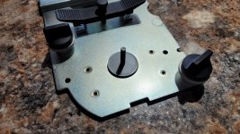
Well not really, but it's not perfect. My latest iteration of the adapter base fits both the LR32 base and the router well. I do want to tweak a couple hole locations which will give more allowance for centering the router on the adapter base. But all the router mounting screws fit now so really wouldn't have to change anything but it could be better so it will be because at this stage I have the time to do it so why not.
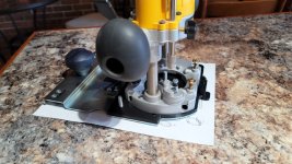
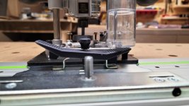
With the router and adapter mounted on the LR32 base in the orientation I normally use the router, and I would suspect most do, is with the plunge lock lever on the left and to the back away from the user. The dust collection adapter for the plunge base exits on the left rear also in this orientation. That's where the problems start (see attached photos).
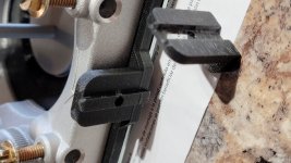
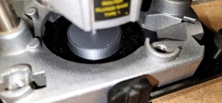
The dust collector hits the top of my knob by about 1mm. I will change to a different knob, no biggie there, just need to print a different style nut. That will let the dust collection adapter seat fully on the base the way it should, but that makes the second interference issue even worse. The dust collection adapter contacts the flip lever on the LR32 base (see photos) and it will be worse once the dust collection adapter is in its proper position.
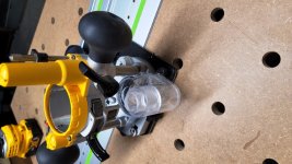
So I though well just turn the router around 180 and try that. But that configuration has the same interference between the knob and dust collection adapter. The interference with the flip lever on the LR32 base is removed, so this will work. And it gets the dust adapter out of the way of the flip lever so you can operate it normally. Even if the dust collection adapter cleared the flip lever it would make tripping the lever difficult on the left hand side. I know that would bug me and I am sure most of you too. Only way around that is to customize the dust collection adapter which I have no plans to do.
I can use it just fine the way it is without dust collection, but I wouldn't want that.
My version of pin lock works well. I used to use a scrap of 5mm ply to hold the pin up so I could slide the base along the guide rail. Saw that trick on here from someone years ago. Sorry I don't remember who first posted it on here. The 3D printed piece doesn't work any better than the ply did, just figured I'd make one. I'm reprinting my centering mandrel in Red so it will stand out when it's installed in the router.
So more tweaking when I get time. Need to hunt down a style of knob or wingnut that will have clearance for everything.
 DCW600 Adapter Plate Bob_D_2-17-2022 (1).jpg153.4 KB · Views: 380
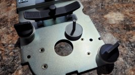 DCW600 Adapter Plate Bob_D_2-17-2022 (2).jpg143.7 KB · Views: 323
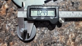 DCW600 Adapter Plate Bob_D_2-17-2022 (4).jpg152.8 KB · Views: 334
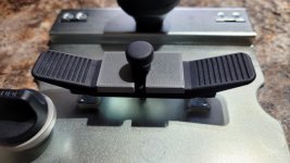 DCW600 Adapter Plate Bob_D_2-17-2022 (6).jpg103.8 KB · Views: 306
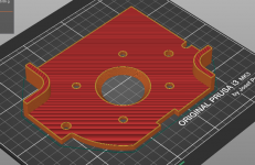 DCW600 Adapter Plate Bob_D_2-17-2022 (8).png209.6 KB · Views: 391
")