DeWalt DCW600 Cordless Router to LR32 Base Plate Adapter

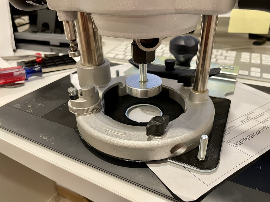
I call it a pin lock but I don't remember what it was originally named if anything. I say pin lock because I use it to lock the pin up on the LR32 base so I can slide the base along without engaging the holes in the rail.

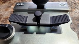
Like I said my first was made from a scrap of 5mm ply years ago. This one in PLA works the same, no added benefit over a scrap of ply, just looks better.

I put it on Thingiverse for non-commercial use.https://www.thingiverse.com/thing:5255185
 

Attachments

  • DCW600 Adapter Plate Bob_D_2-20-22 1041  (1).jpg
    DCW600 Adapter Plate Bob_D_2-20-22 1041 (1).jpg
    95.6 KB · Views: 272
  • 20220217_142007.jpg
    20220217_142007.jpg
    104.4 KB · Views: 220
  • 20220217_142015.jpg
    20220217_142015.jpg
    149.2 KB · Views: 226
Do you anticipate being able to remove the motor from the plunge base and maintaining concentricity with the LR-32 baseplate? That would be really fantastic if so.

 
DynaGlide said:
Do you anticipate being able to remove the motor from the plunge base and maintaining concentricity with the LR-32 baseplate? That would be really fantastic if so.

Yes, if the plunge base remains attached to the adapter plate then alignment is not lost. You can pull the motor, change bits, and reinstall and alignment should be good. It would be a pain to change bits in place. Alignment between the router and the LR32 base is made at the adapter using the same two M6 studs that are used to clamp the OF1400 to the base.

My side job (laundry room refresh) is taking time away from more important things like finishing this adapter. :-)

I wanted to use my Bosch laser level to mark out for the cabinets on two walls, but my tripod is busy with my video camera mounted on it and I didn't want to take that apart so I thought I'll use my big camera tripod. It was made for a 4x5 view camera that weighs about 10 pounds so should be able to hold the laser level. But problem is the mount is 1/4-20 like most camera tripod mounts and the laser level is 5/8-11. So I designed and printed up an adapter. I couldn't find one online so made my own. The threads still amaze me, especially the smaller ones like 1/4-20. The adapter has a 1/4-20 internal thread and 5/8-11 stud to screw into the bottom of the level. The standard thread on survey equipment.
 

Attachments

  • 20220220_165707.jpg
    20220220_165707.jpg
    114.7 KB · Views: 211
  • 20220220_165723.jpg
    20220220_165723.jpg
    82 KB · Views: 212
  • 20220220_172002.jpg
    20220220_172002.jpg
    168.1 KB · Views: 227
Very nice. You'll have to put me down for a DeWalt adapter setup when this is all fleshed out.

Matt

I'm also wishing I knew how to use a 3D printer after all this.
 
SOHN, that's where I'm learning. :-)

And YouTube of course. Toughest part is learning the modeling software.

I didn't know anyone who had a 3D Printer, at least when I got mine. Now my daughter and her husband have one so I lost one of my reasons for getting the printer in the first place which was to make stuff for the grandsons. Now he just gets Mom or Dad to do it. :-)

But I still have the older grandson by the other daughter to spoil with printed stuff so all is not lost. :-)

I put the tripod adapter on Thingiverse and in less than an hour there have been over 60 downloads.
 
afish said:
If im only spending 100-150 its easy.  I was even going to get a 2nd LR32 base plate to have one router for 5mm and one for hinge cup holes.

Well with the plunge base mounted to the LR32 base you can buy a second router and just swap the two router motors with different bits. That would be super fast and convenient.
 
Curious if there's enough space if you rotate the router 90.  The knobs do come off if you break the blue threadloc - I've taken one of mine off and replace it with smaller Festool m8 knob because of previous clearance issues with a jig.  I've also run it without one knob and it actually feels fine (if not better).  Just need the one with the lever. 
 
woodferret said:
Curious if there's enough space if you rotate the router 90.  The knobs do come off if you break the blue threadloc - I've taken one of mine off and replace it with smaller Festool m8 knob because of previous clearance issues with a jig.  I've also run it without one knob and it actually feels fine (if not better).  Just need the one with the lever.

That may be possible, but since the bolt pattern is rectangular not square, it would require four more holes in the same adapter plate for which there may not be enough clearance with the other four holes. In which case it would mean having a separate adapter plate for each position or just one. I guess it could work either way, I did not consider that.
 
I agree with Dynaglide about the 3D printer. Wish I had one.  May have to figure a way.

Rusty
 
Richard/RMW said:
After some initial fiddling I haven't had to adjust anything, it just works.
RMW

Lucky you, I wish I could say the same of my 3v2, I've had nothing but trouble. Mechanical issues like part cooling fan failure, static shocks, layer shifting possibly from board overheating.

If anyone's looking for a real bargain Microcenter has been having the Ender 3 Pro for only $99 fairly often this year with coupon.

Agree that Fusion is like quicksand, not because it sucks me in to wanting to make cool stuff... but because I often find myself "stuck" on how to do stuff.  [big grin] I'm a novice, though.

That being said I manage to whip together a quick test for my DW618.

fusion-model.png


IMG-5955.jpg


IMG-5956.jpg


Needs some tweaking as expected, but thank you [member=60461]Bob D.[/member] for the great idea and inspiration!

 
Looks good. Since your router base overhangs the LR32 base you might look into including a pad to support that extended portion of the base. Wouldn't have to cover the entire sector just something out near the edge that reached down to the same plane as the pads on the bottom of the LR32 base. that would eliminate any possibility of applying a little too much downforce over that area and lifting the router off the rail.

You eventually need to extrude your adapter plate out a few mm so you have room for the screw heads. Print with the top side down for best results and that would be a requirement if you add the support pad I mentioned above.

I would make the top (now your bottom layer for printing with the piece inverted) thick enough that it is solid to the depth of the screw counterbores. So the first 2mm or so should be solid. PLA is what I have been prototyping with, but may go with PLA+ or PETG for the final print.
 
[member=60461]Bob D.[/member] good idea on the support pad. I haven't used it on the rail yet, so not sure how tippy it will be. Can't hurt though.

Yes, these test prints are only 2 layers thick. You can actually see through the plastic it's so thin haha. Just trying to test fit the holes before wasting a bunch of filament. The real one would be extruded about the same depth as the stock acrylic base, like you did, and counterbored for the mounting screws like you said.

Another thing, I bought an Amana 1/2"-8mm collect reducer for the Festool centering mandrel, but for some reason it's an extremely tight fit, so much so that I couldn't get it installed all the way, so I'll probably be copying you on a 3d printed version of that, too!
 
nicholam77 said:
Richard/RMW said:
After some initial fiddling I haven't had to adjust anything, it just works.
RMW

Agree that Fusion is like quicksand, not because it sucks me in to wanting to make cool stuff... but because I often find myself "stuck" on how to do stuff.  [big grin] I'm a novice, though.

Yea my typical F360 sketches would cause an engineer-type to cringe, but I manage to output usable stl or svg for my uses. Everything takes nine times as long as it would if I knew what I was doing, but again, results...

You should see my attempts at hand sketching.  [tongue]

I am eagerly awaiting someone to post a stl to play with though.

RMW.
 
nicholam77 said:
Richard/RMW said:
I am eagerly awaiting someone to post a stl to play with though.

You can look at mine if you'd like. I'll probably upload to Thingiverse when its done, but this link has the f360 file, step, and STL so far.
https://www.dropbox.com/sh/9aiczm5bspfl080/AAB4A_A200ekJxmZQSVcORhTa?dl=0

Thank you! Quiet today so I plopped your STL into Cura and have it printing now. Probably get a chance to fiddle with it tomorrow, will provide feedback.

RMW
 
I'll just be sitting here waiting for one of you smart fellas to make me one of these sub bases once it's all fleshed out.
 
I haven't done any more with mine. Been busy with other projects and family stuff.
 
Richard/RMW said:
You can look at mine if you'd like. I'll probably upload to Thingiverse when its done, but this link has the f360 file, step, and STL so far.
https://www.dropbox.com/sh/9aiczm5bspfl080/AAB4A_A200ekJxmZQSVcORhTa?dl=0

Thank you! Quiet today so I plopped your STL into Cura and have it printing now. Probably get a chance to fiddle with it tomorrow, will provide feedback.

RMW

FYI mine is for my larger DW618 plunge base, not the DCW600 like Bob's. And my model is incomplete, pretty much have just been testing the hole positions so far which is why it's only 1mm thick. I can repost something once I finish it, but especially if you have the smaller router [member=60461]Bob D.[/member] 's design probably makes more sense!
 
Back
Top