Dining room carver chairs - Take 2

derekcohen

Member
Joined
Jun 22, 2008
Messages
936
About a month ago I began a thread about designing and building two carver chairs to accompany the 6 bentwood chairs we have owned for the past 40 years. The chairs were purchased all those years ago along with a table, which is around 200 years old. We need a larger table, and time has come to replace it and add two more chairs.

8.jpg


The table planned will be a modern version of this, in Hard Maple and round Jarrah legs. The carver chairs need to match the table and blend with these chairs. Our taste is minimalist, Mid Century Danish, modern. An example of the lines I seek is this sofa table I built several years ago ...
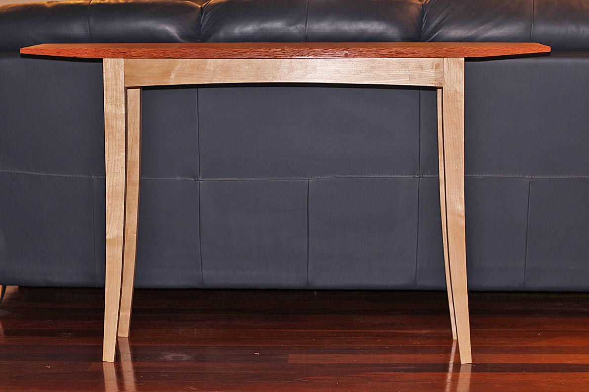
28a.jpg


So I started thinking about the chairs I would build, and I took inspiration from this picture ...
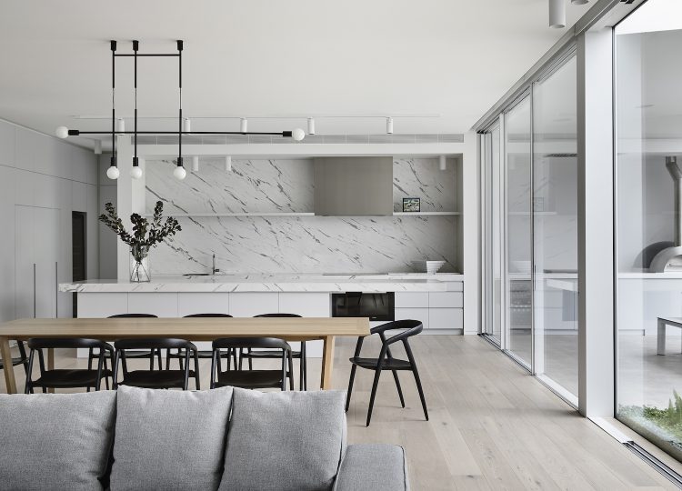
est-living-sorrento-light-house-wolveridge-architects-3-750x540.jpg


... and began to evolve a design along similar lines. The 8 legs were started (just need rounding) and the seats carved, and then the tenons were cut. And that is where the problem arose. I had this idea for integrated tenons into through mortices in the legs. Very few chairs are built like this, and for a good reason - you cannot control for run out in the tenons, and run out make for weak tenons. And that is what I discovered. So I stopped the build, and decided to begin again from scratch.

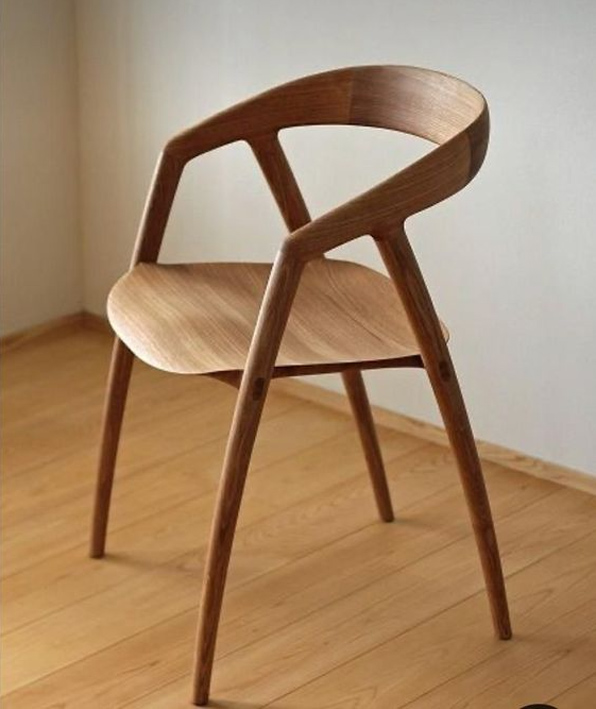
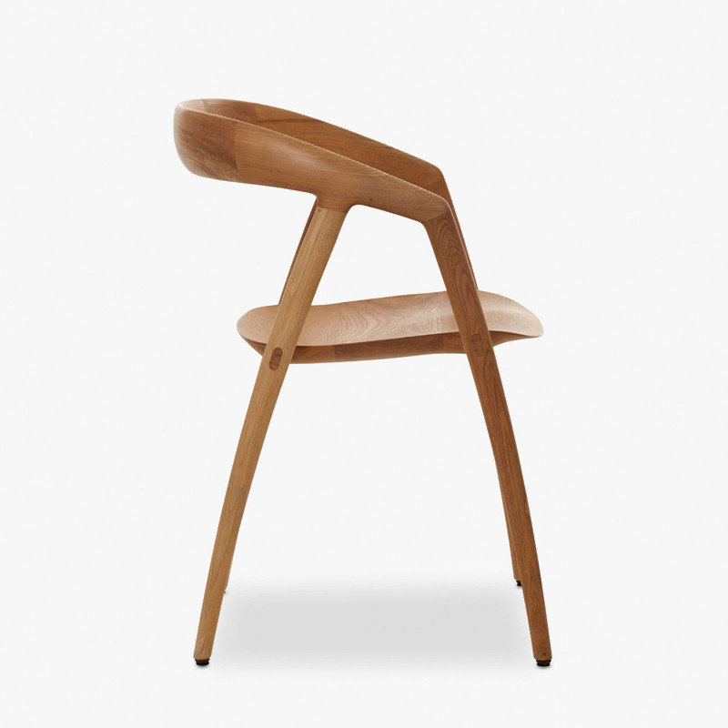
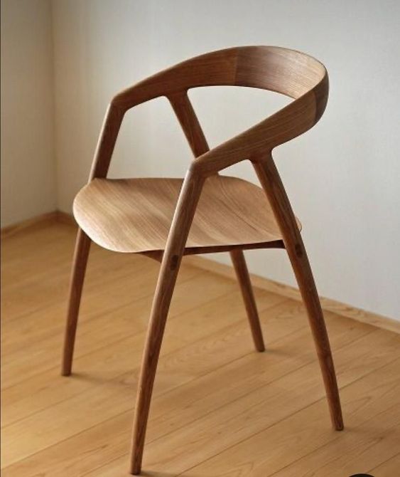
I started looking more carefully at the chair I had come across and had treated rather casually. It has a name: DC 09, and it was designed by the Japanese- Scandinavian duo, Kyoko Inoda and Nils Sveje, in 2011. It is built by the Miyazaki factory in Japan.
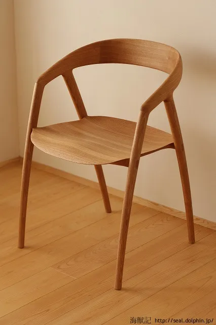
Chair-seat9.webp


There is a challenge here - can I replicate it purely from photos? This is unlikely since one needs to examine an object in three dimensions to discover the subtleties of the design and construction. I have experience of this, having made an exact copy of Hans Wegner's "The Chair" or the "Round Chair" several years ago. What made this possible is that I own an original. One is mine and one is Wegner's ...
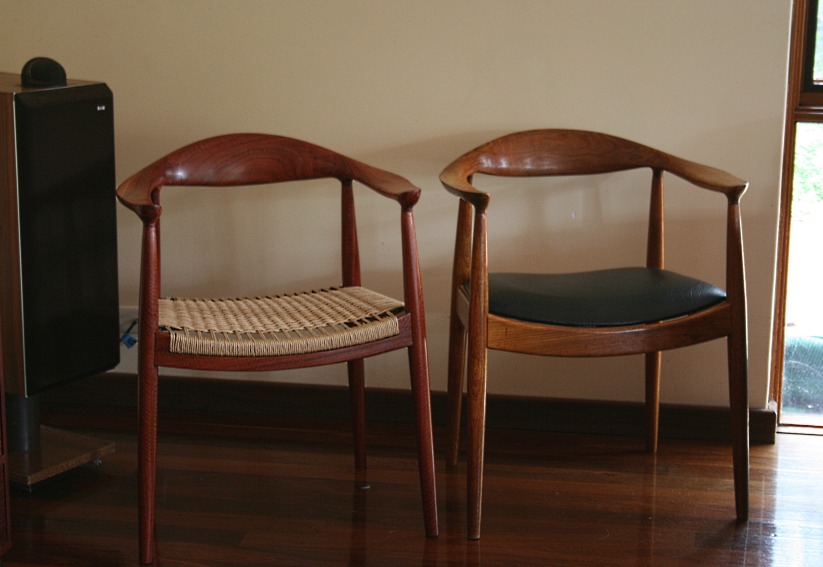
The-Chair.jpg


So the chairs I build will not be exact, but hopefully close. Actually, I am still on the fence about the arms and back and may modify this ... but will will see. We need to start with the seat. That is the key.

Help comes from two video I found ...
=yasuhiromurai
https://vimeo.com/438408781

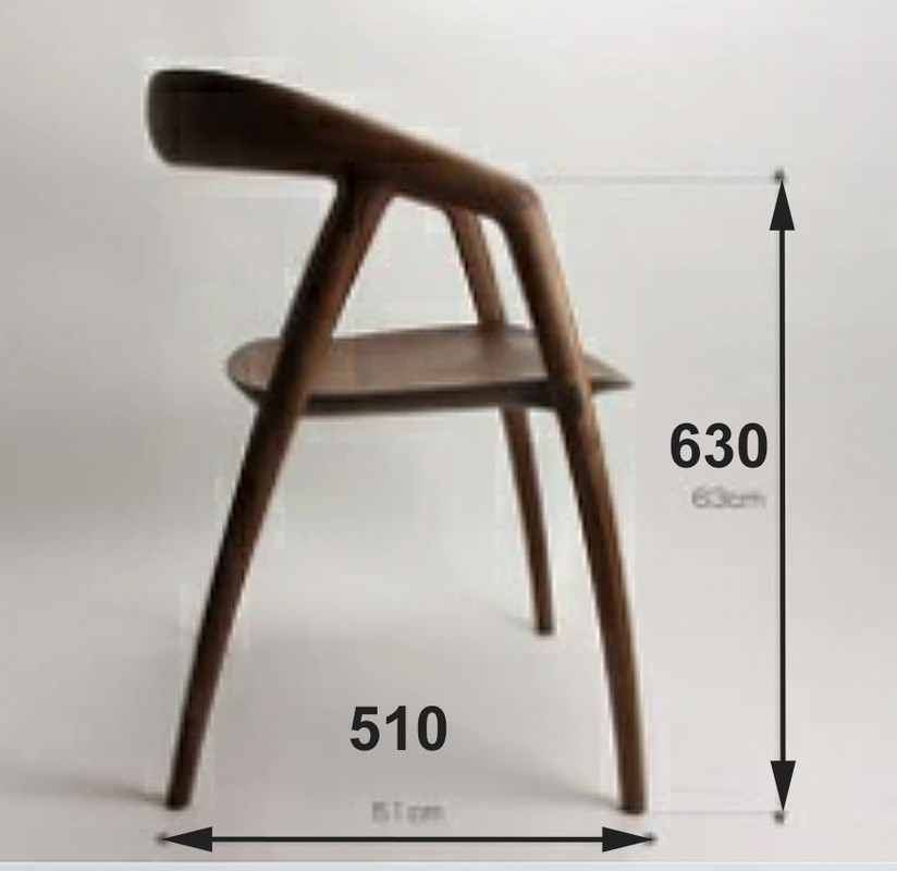
Some dimensions:
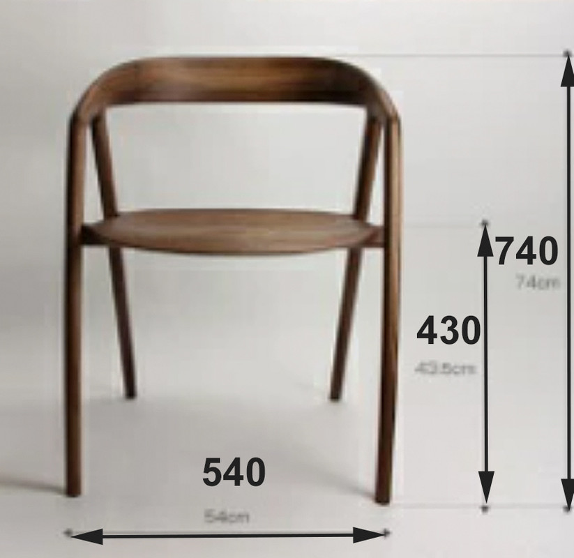
Chair-plan1.jpg


Chair-plan2.jpg


The doors above my bench make a place to pin details and photos ..
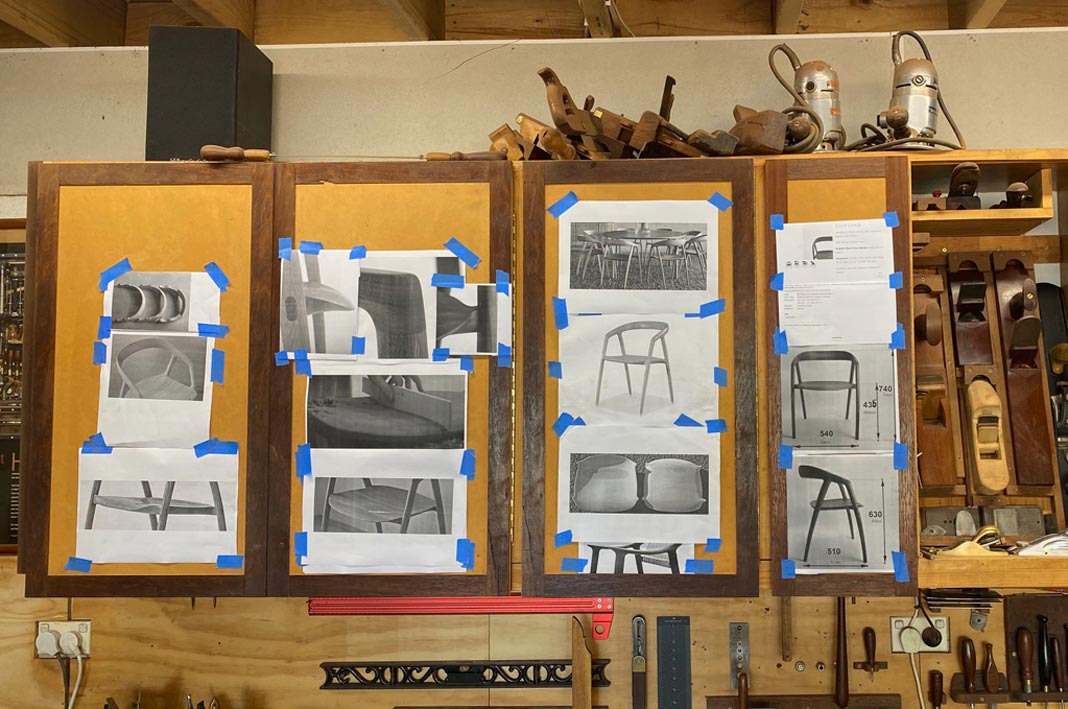
New1.jpg


The seat plan was scaled and drawn using images from the videos and photos.

Two half-templates were created - the first was a straight-sided outline of the seat. The reason for this is that I planned to use loose tenon joinery, which would enable the tenons to have straight grain for maximum strength, and the mortices would be made using a Domino. These would be 30mm long x 10mm wide, in other words would use custom-made loose tenons. The straight sides would make it easier to cut the mortices ahead of shaping the seats.

The second half-template was the actual outline of the seat, and this positions the tenons.
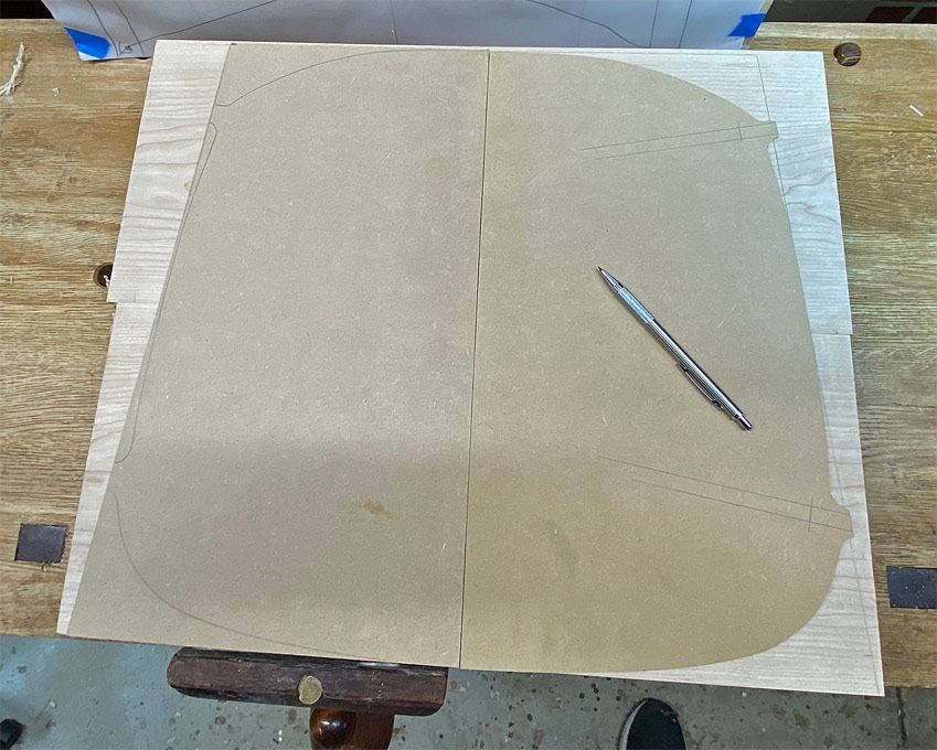
New3.jpg


Here the tenons are positioned ...

New5.jpg


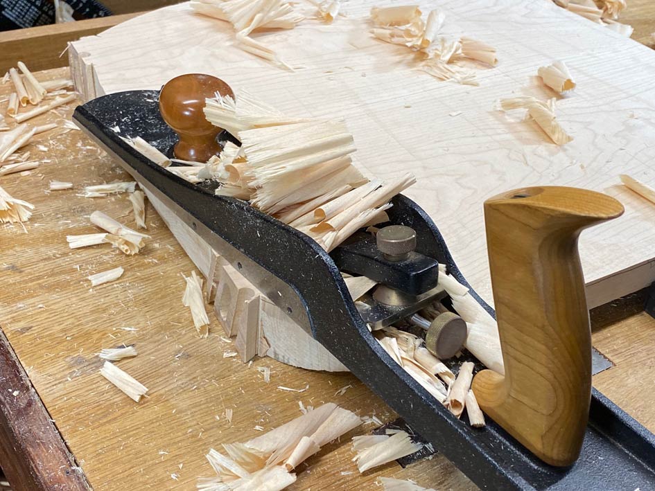
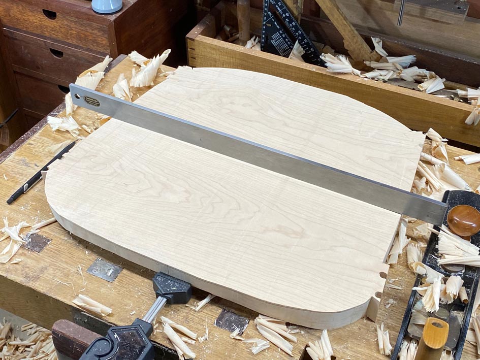
A little jack-planning to flatten the underside of the seat blanks ..
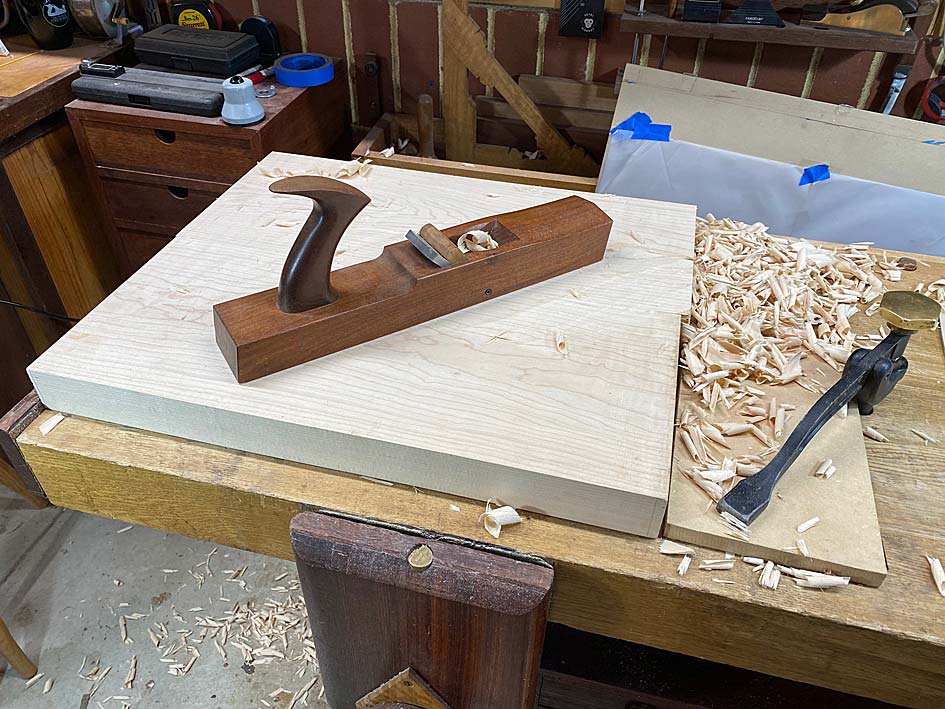
New6.jpg


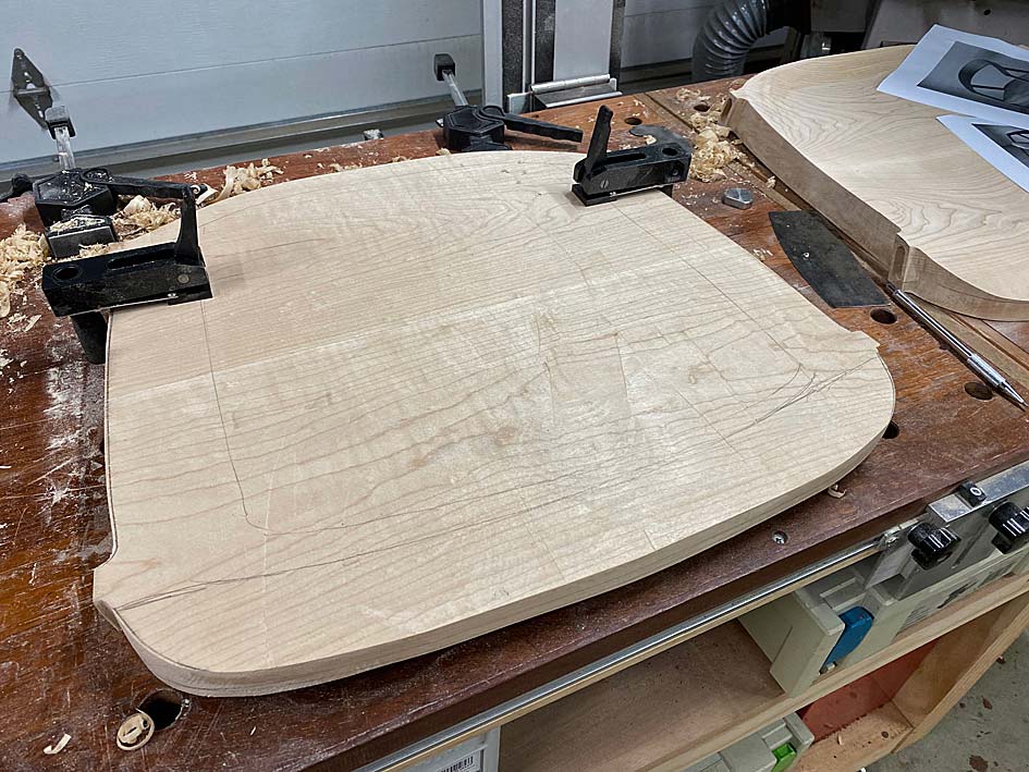
These are now sawn to shape ...

New7.jpg


New8.jpg


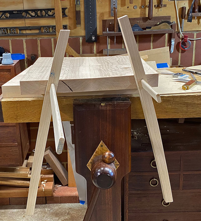
After this was done it became apparent just how the first shaping of the chairs differed from the DC09 design. Here is the first chair along with two legs. In the background can be seen the plan I had made for that build ...

New2.jpg


It looks quite good, with the angles and spacings appearing correct. In fact, they are quite different from the DC09. Below is the DC09 seat below the first seat. You can see the positioning of the legs ..
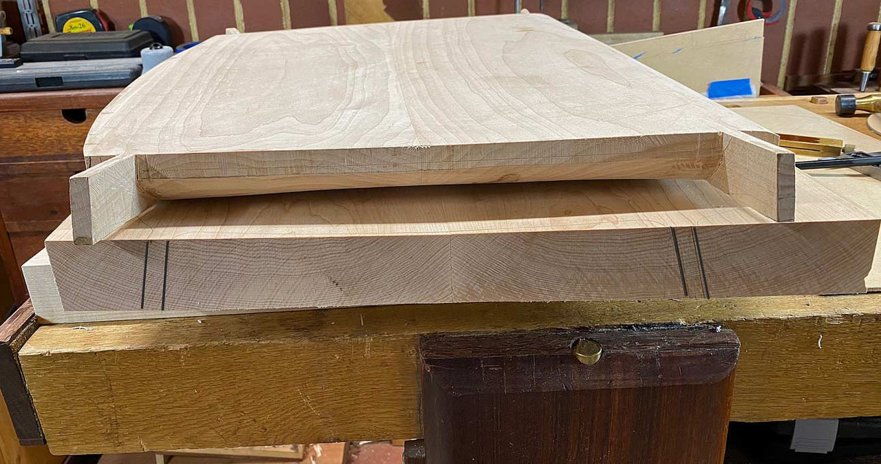
New9.jpg


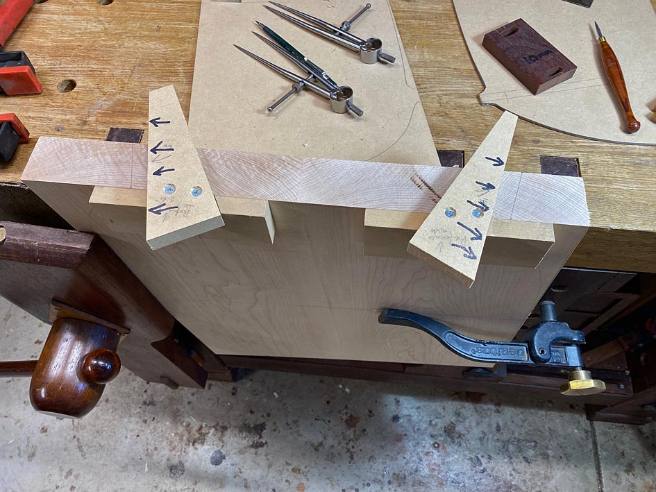
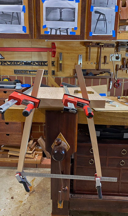
Before I dominoed the mortices, the legs were mocked up to be sure of the angles. I discovered that they should be at 14 degrees and not 10 degrees, as they had been before. In the top right corner you can see a DC09 for comparison ...
New10.jpg


Guides for 14 degrees ...

New11.jpg


Marked and morticed ...

New13.jpg


New15.jpg


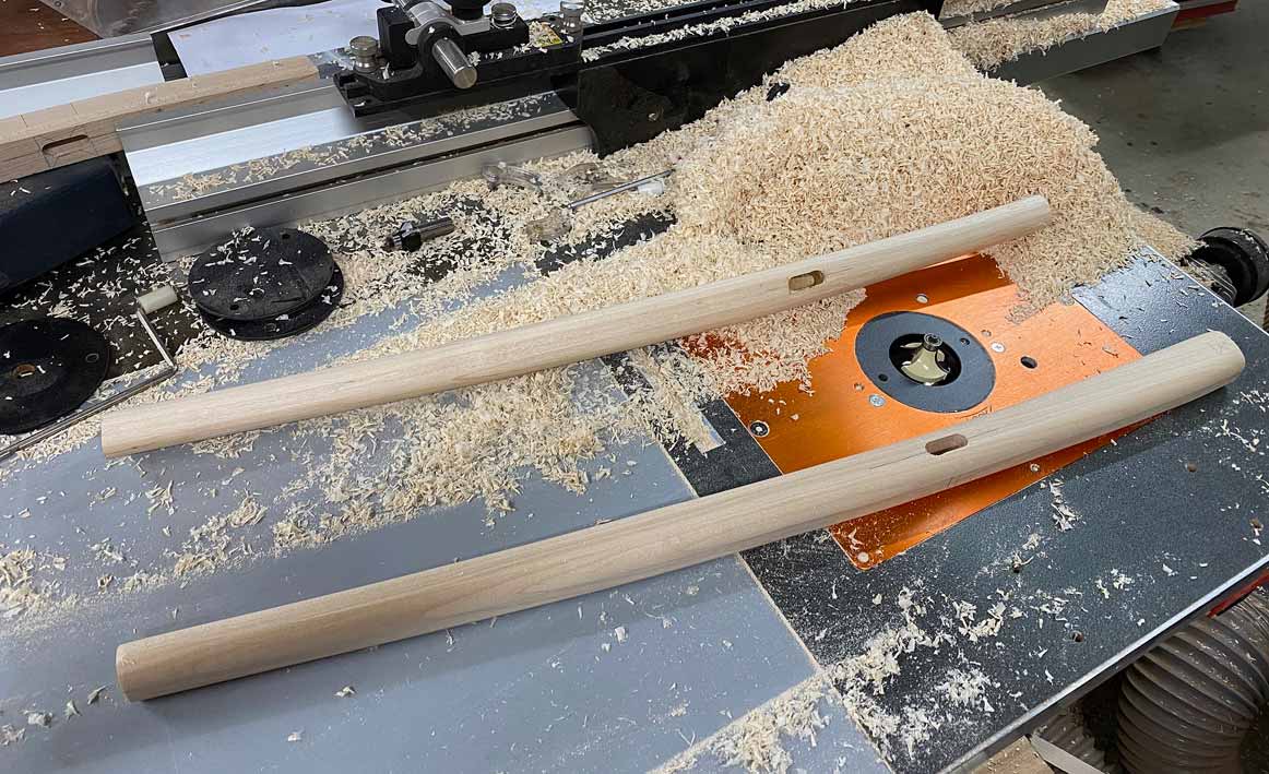
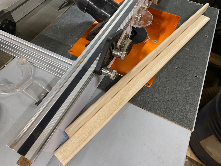
Tenons were made on the router table ...
New14.jpg


All is looking right so far ...

New16.jpg


The rule for chair backs is that thy need to allow for a lean of about 90-95 degrees. I have been thinking about this but decided to set aside this area for later. The priority is to get the seat shape correct - in three dimensions. - and its relationship with the legs (which were shaped in the first build - they are substantially correct, other than the upper ends being around 28mm against the - estimated - 40mm of the DC09. I will decide on whether to keep or replace these later). I have left the legs 1" longer in the lower half to adjust the tilt of the seat (the seat sits 18" off the ground and the ones I made previously are 19" in this respect).

I did stand the old chair along the table, and noted how low the arm rests were in reality - actually an ideal height for comfort. I do have some ideas how they may be "improved" aesthetically .... but this for later.

All advice gratefully received.

Regards from Perth

Derek
 
Derek, this is very interesting so far. I've been looking at Hans Wegner's chairs for some time and thinking of building one of his designs. Curious as to where you got your dimensions of the DC09 chair. Were you able to see one and measure it or did you determine them from a perspective drawing you created from photos? I've done this with casework but never tried it with a chair due to the numerous compound angles. Can you share how you developed your drawing?

Thanks for documenting this project.
 
Mortiser said:
Derek, this is very interesting so far. I've been looking at Hans Wegner's chairs for some time and thinking of building one of his designs. Curious as to where you got your dimensions of the DC09 chair. Were you able to see one and measure it or did you determine them from a perspective drawing you created from photos? I've done this with casework but never tried it with a chair due to the numerous compound angles. Can you share how you developed your drawing?

Thanks for documenting this project.

Mortiser, this is a important area. What I do is explore the videos and all photos, and then screen save relevant examples. From this I estimate or calculate size, approximate dimensions, and refine these over multiple examples. Here are some of the photos I used ....


Regards from Perth

Derek
 
Thanks Derek. You obviously spend a lot of time researching your projects. And you've obviously honed your skills in determining dimensions and angles from photos. I have a lot of screenshots now but have not settled on a particular style yet. I like the chair you have chosen and am working on narrowing my selection. I may pick the one I like most and then make some slight modifications. I'll probably have to spend a little more time on a chair drawing as I see it as my most challenging plan development yet.

I'll keep watching your project. Thanks for taking the time to let us proceed through it with you.
 
A question about loose tenons

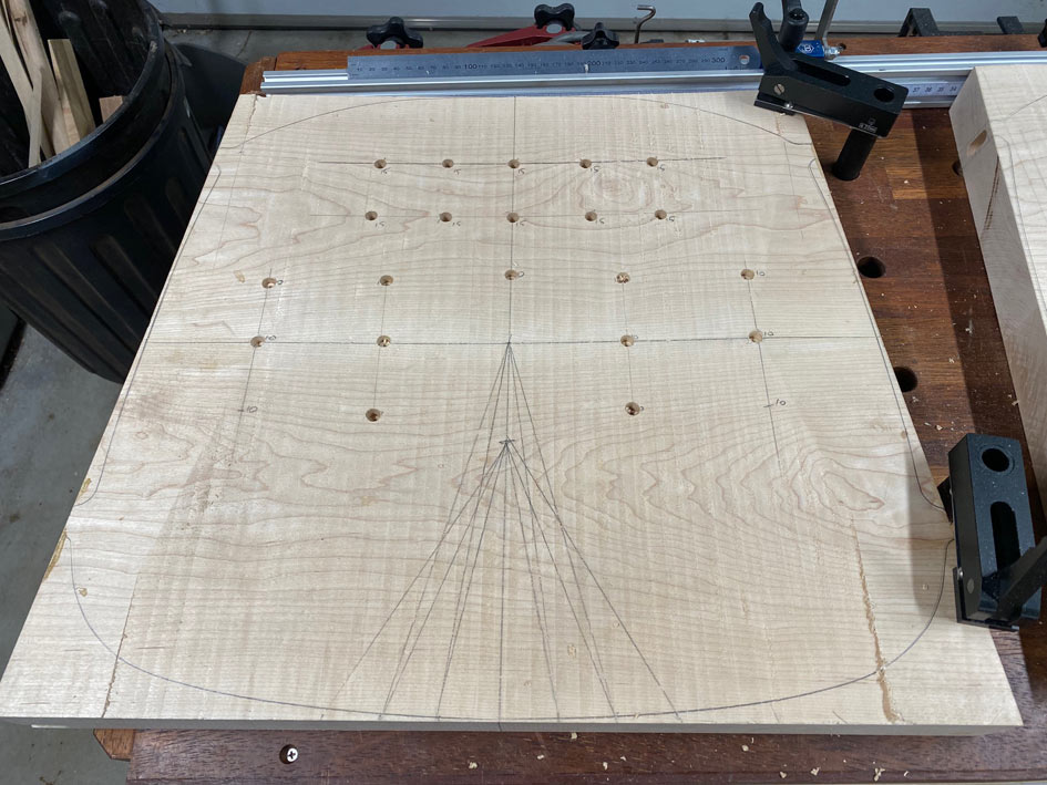
The legs will be joined to the seat with loose tenon mortice-and-tenon joinery. The tenons are Hard Maple, as with the rest of the build. I am in the process of choosing the stock for the 10mm wide x 30mm long tenons. The aim is to ensure that these are the best for a chair. Not any other purpose, but a chair.

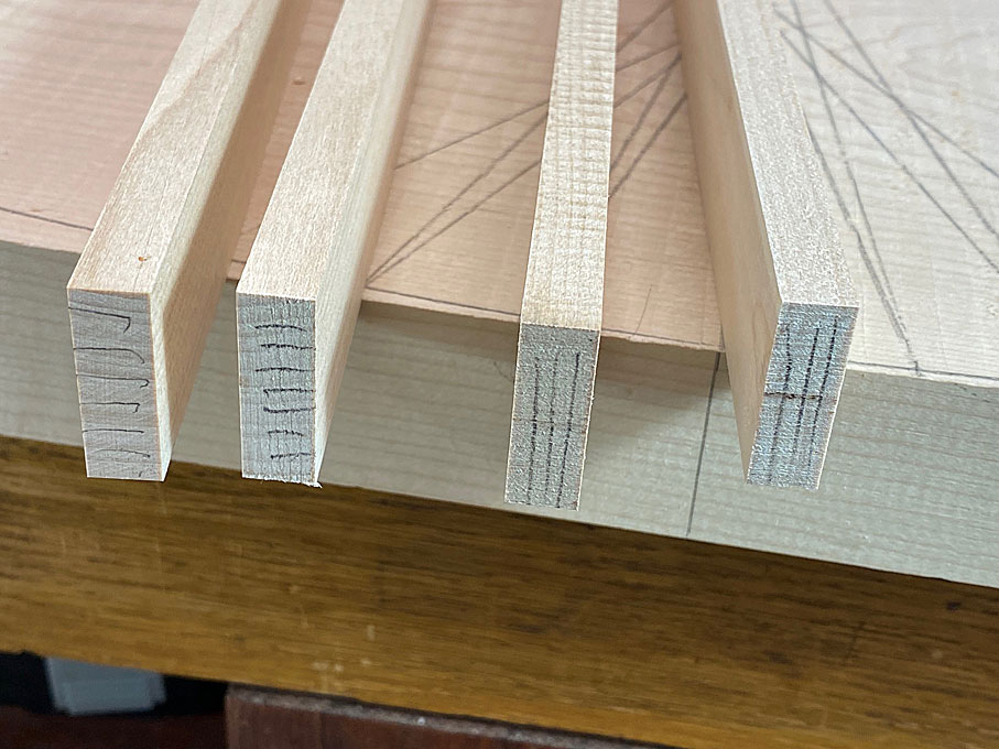
The issue is grain direction: is it better to have the grain running horizontal or vertical?

Tenon1.jpg


Vertical grain should offer more rigidity, while horizontal grain more flexibility. While is preferred - your opinion?

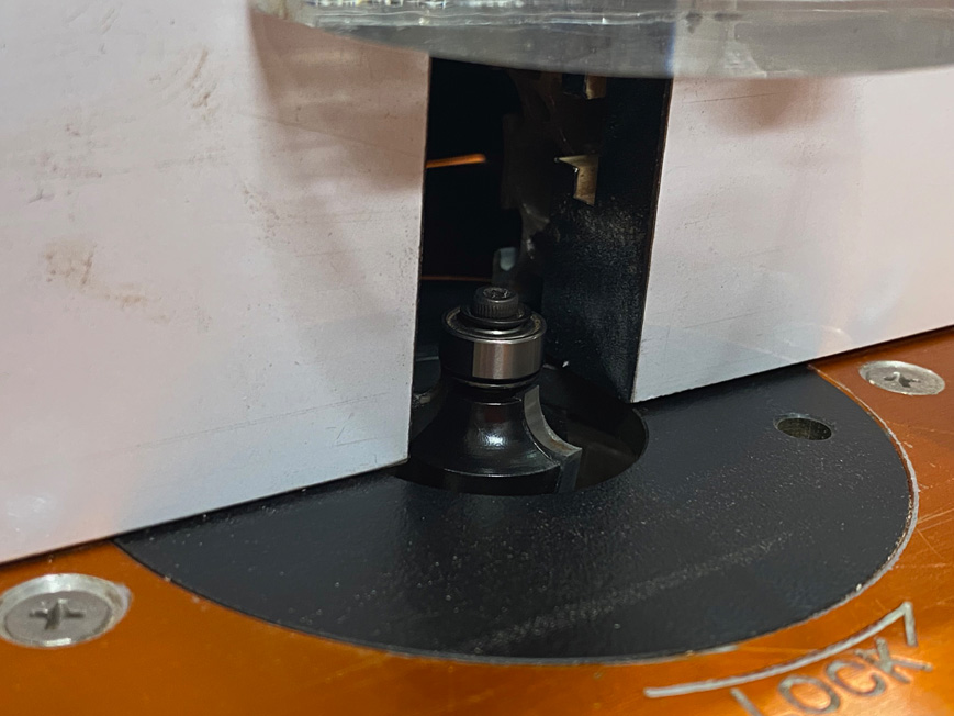
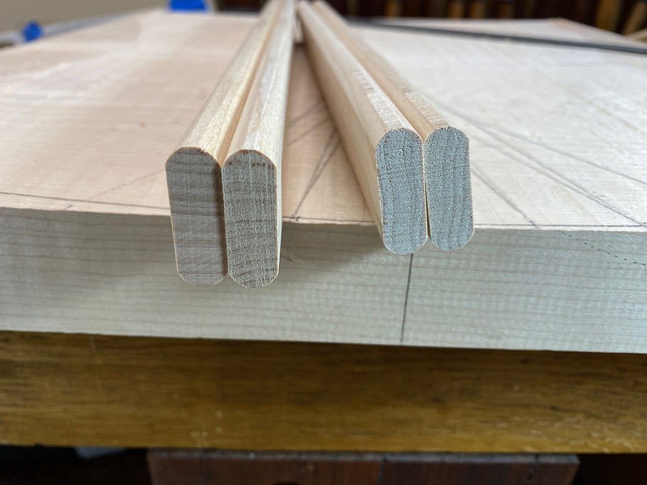
The square stock is shaped on the router table ...

Tenon2.jpg


Tenon3.jpg


This is how it will look in the leg through mortice (minus the wedge and the rounded leg) ...

Tenon4.jpg


Regards from Perth

Derek
 
Beautiful work, as always, [member=4358]derekcohen[/member]
I honestly don't know which way is stronger? but I think it would orient then so that the grain is aligned with the leg as much as possible, with the hope that it would disappear, rather than draw attention.
Those chairs are so flowy and shapely that I wouldn't want to interrupt that.
That's just me and my OCD though, if you find that it is weaker that way, ignore my ramblings

In some cases, I like to draw attention to joinery, just not there.
 
Thanks CRG. I do plan to do this - keep the grain of the seat and tenon aligned. (= vertical). Firstly, I think that will be stronger and have less flex. Secondly, the wedges will work in the traditional manner.

Regards from Perth

Derek
 
This is a long post with a good many photos. Treat them like a comic strip - flip by. It's just that there is so much more than one might realise that needs to get done when carving a seat. It is a 3D construction, and more complicated than joining square sections. This will become apparent as we progress.

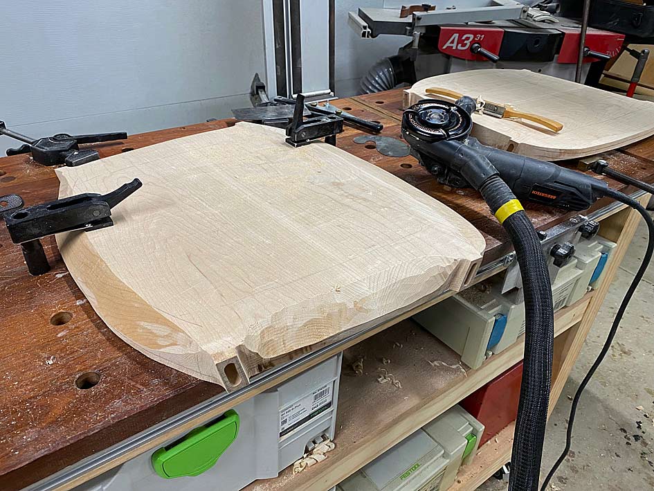
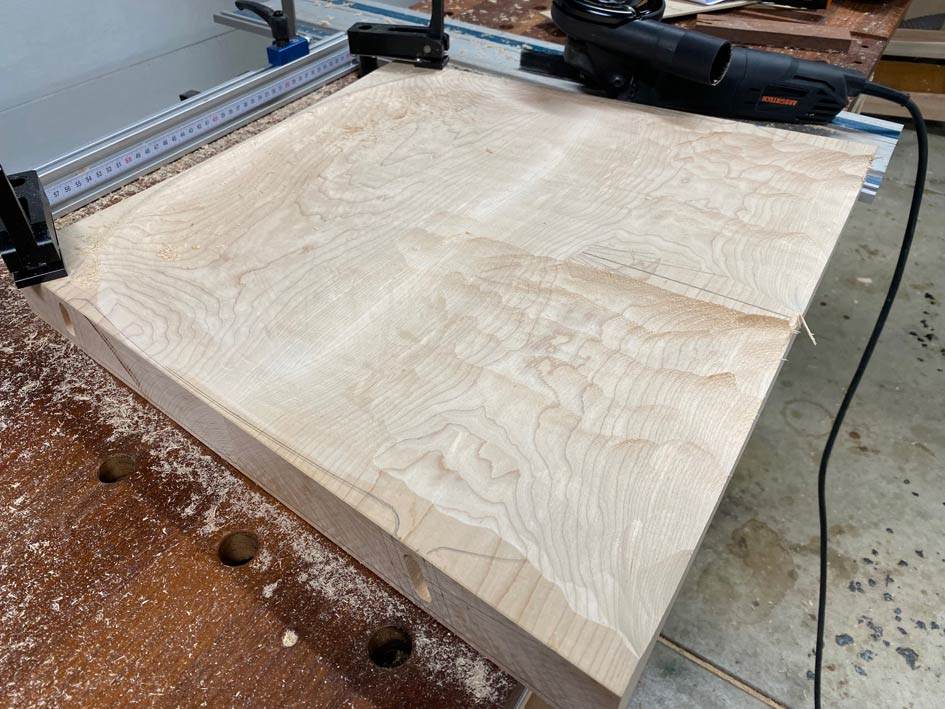
These are the two seats. Both have been prepped with drilled holed to carve to depth. My plan is to work two seats alongside one another, completing a section on one and then duplicating it on the other, moving on, back-and-forth. The first stage is to power carve the rear of the seat using the Arbortech ...

Build1.jpg


Build-dots.jpg


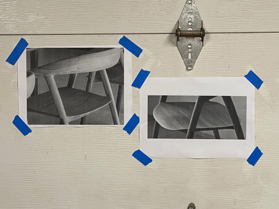
Garage doors make for a handy white board to hang photos. These are the seats, and the angles provide the needed guidance.

Buil2.jpg


First shaping ..

Build3.jpg


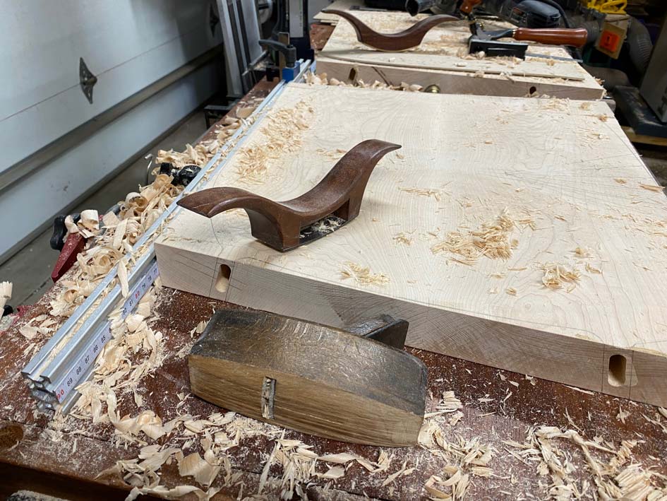
It's rougher than it looks. A travisher begins the process of smoothing the curves ..

Buil4.jpg


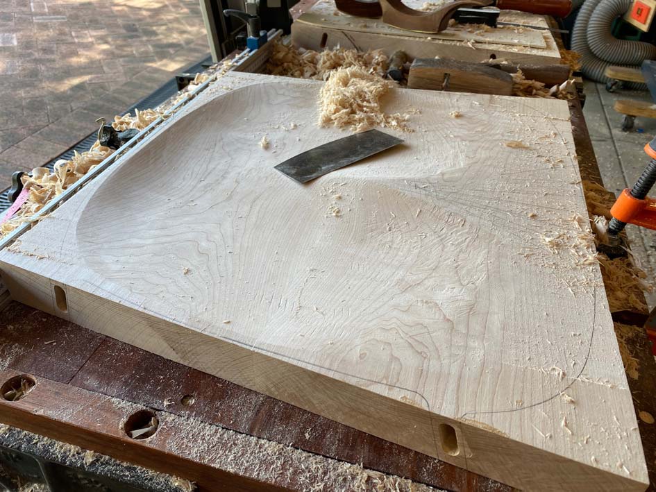
Every now-and-then a scraper will refine the tear out ...

Build5.jpg


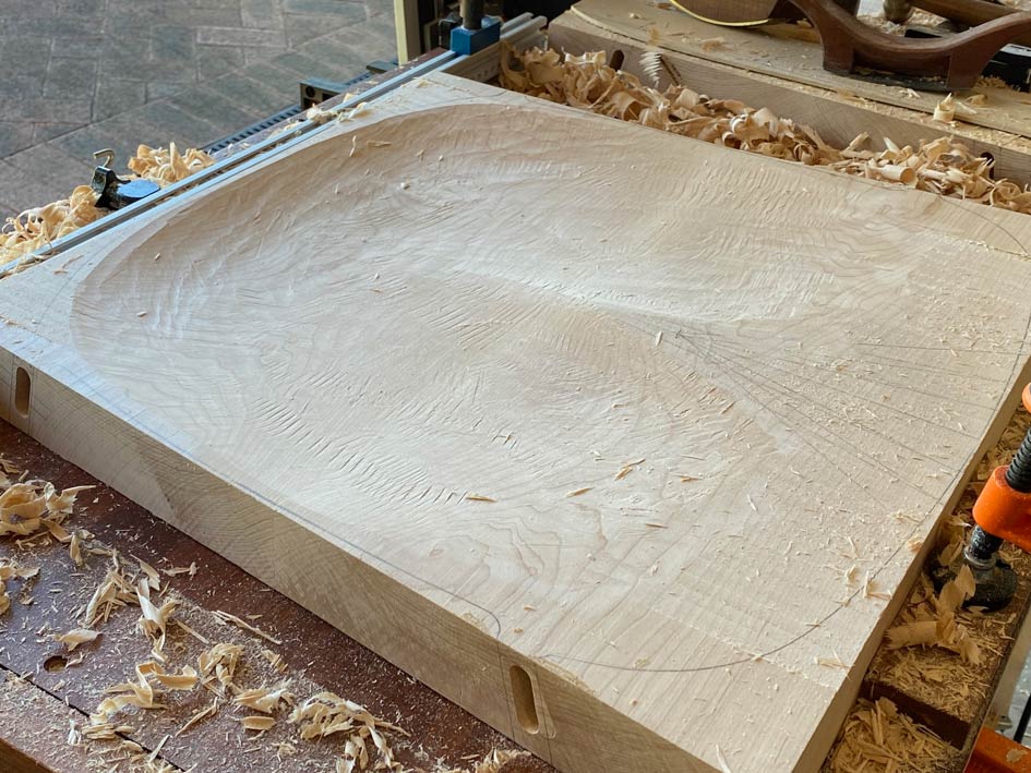
We begin the front section of the seat now, again using the Arbortech carver ...

Build6.jpg


And refine with a travisher ..

Build7.jpg


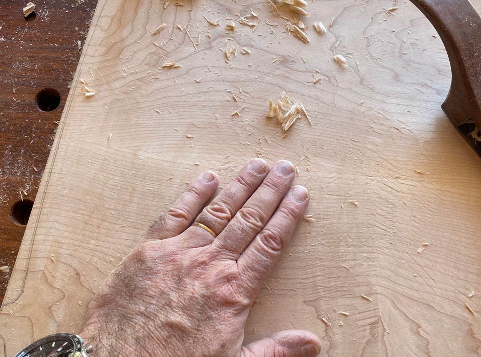
... always feeling the surface with a hand to detect any uinevenness ...

Build8.jpg


It is beginning to resemble the photos ...

Build9.jpg


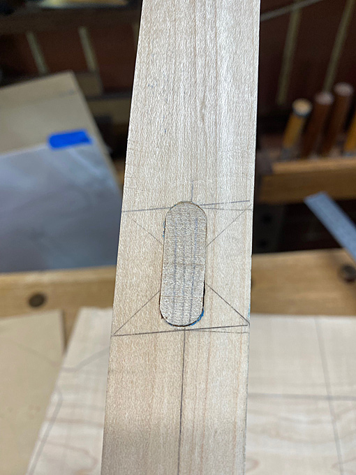
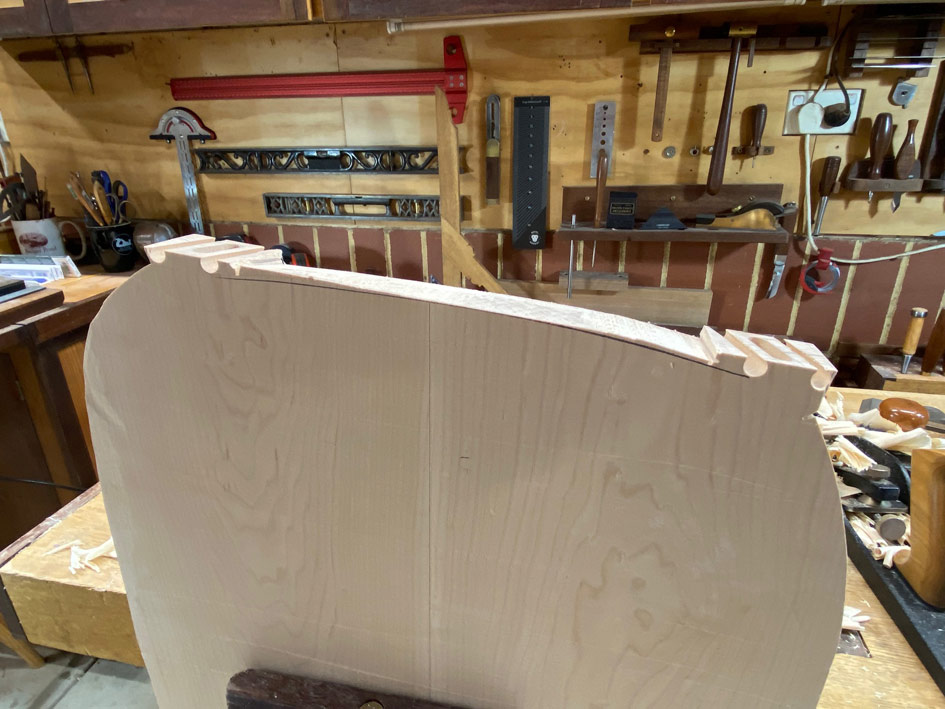
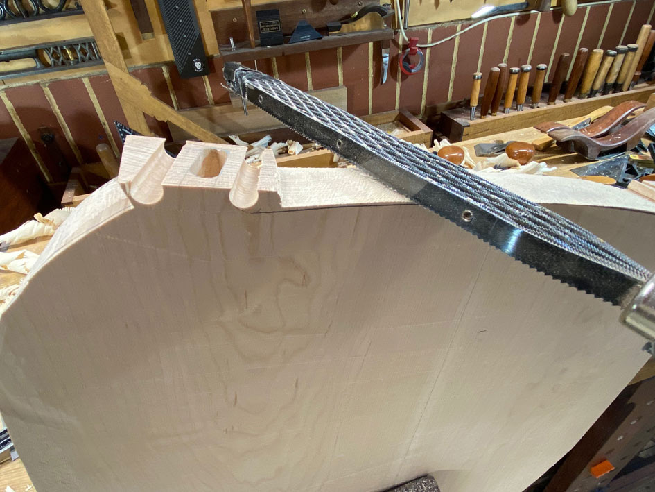
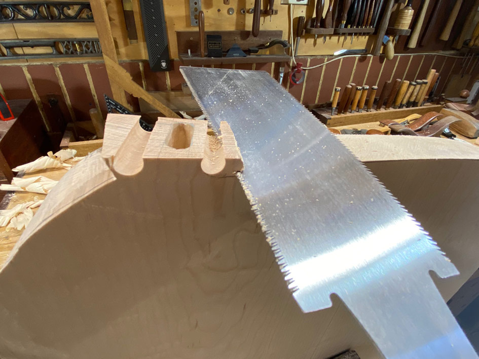
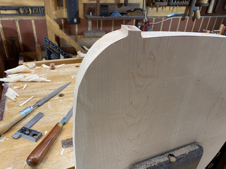
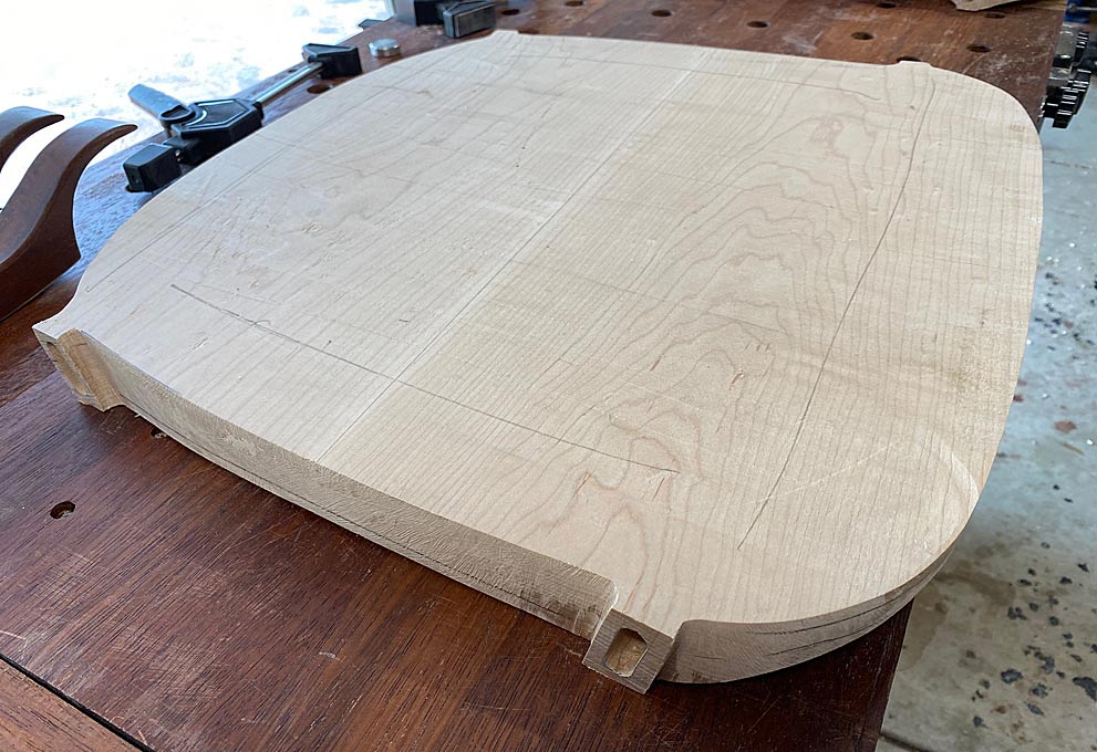
At this stage it is time to cut out the seat surround, but before this can be done, the mortices (for the loose tenons) need to be preserved. This is not straight forward as they angle at 14 degrees. As a result, it is not possible to saw from end to end. The area around the tenon will require extra shaping.

My plan was to drill alongside the base, which would refine it and also create a curved root ...

Build10.jpg


Build11.jpg


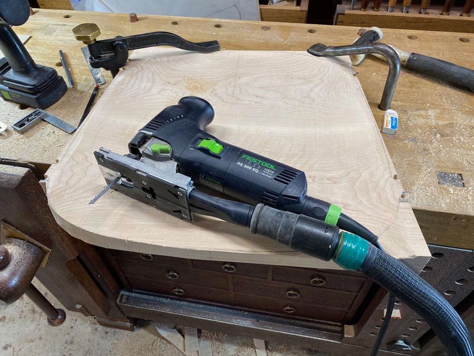
Then as much as possible was sawn away with a jigsaw ...

Build12.jpg


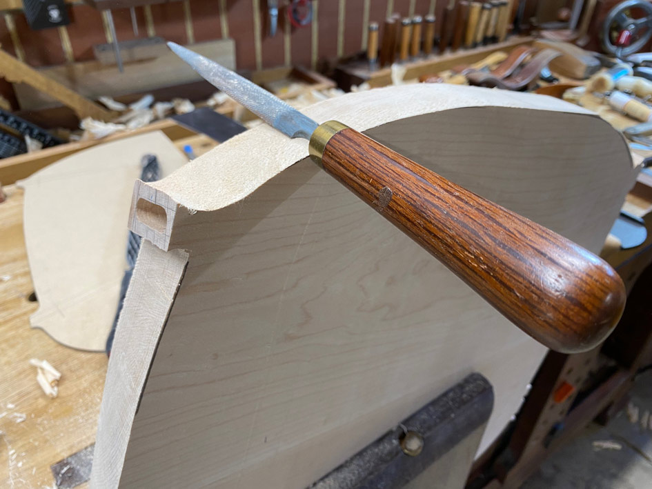
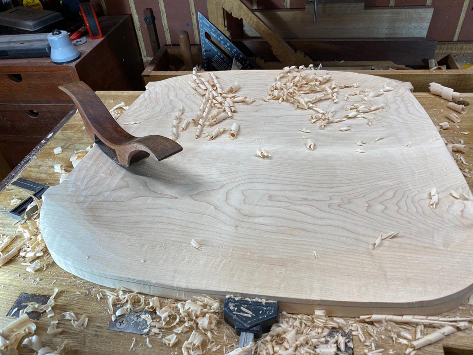
Time to refine the front section and tenons. To do this, the underside of the seat needed to be made perfectly flat: this will provide a reference side to mark the boundaries at the front for carving to; also, taking down the bottom will define the bottom of the tenons ..

Build13.jpg


Build14.jpg


The shape of the underside is estimated using the templates for the top side ..

Build15.jpg


.. and refined with a rasp ..

Build16.jpg


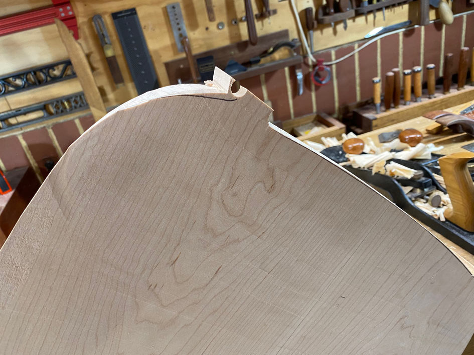
Waste sawn away ...

Build17.jpg


.. and shaped ...

Build18.jpg


Again and again ...

Build19.jpg


Build20.jpg


Finally the front of the seat can be shaped as it flows from the end of the tenons ...

Build21.jpg


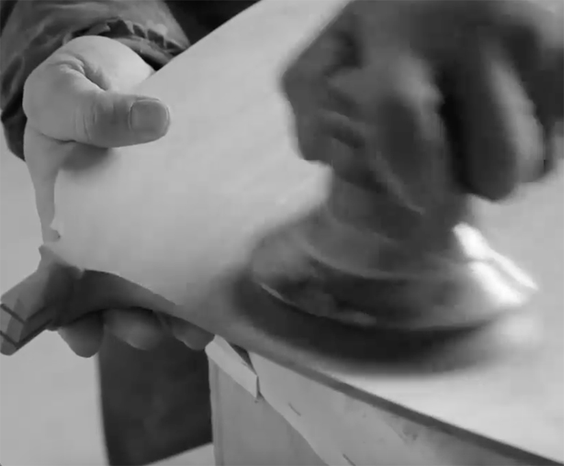
With raking light, the tear out and bumps are more easily seen, and now sanded down with 80 grit (more will be done much later on) ...

Build22.jpg


Build23.jpg


And that's it for today. Underside shaping to come.

Regards from Perth

Derek
 
Thanks Derek. Enjoying watching the process, and the progress. Appreciate all of the photos with explanation.
 
Neil, I built the original seats with integral tenons, and then decided that they were a poor risk as the tenons showed grain run out. What may not be apparent in the photos is that the tenons angle at 14 degrees, which adds to the chance of run out. With loose tenons, I can choose the stock and orient the grain for maximum strength.

Regards from Perth

Derek
 
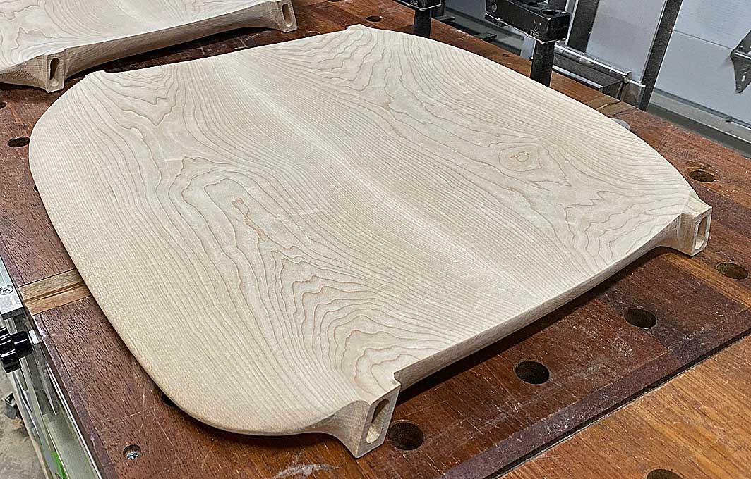
Time to finish the seats ... sort of ... well, very close.

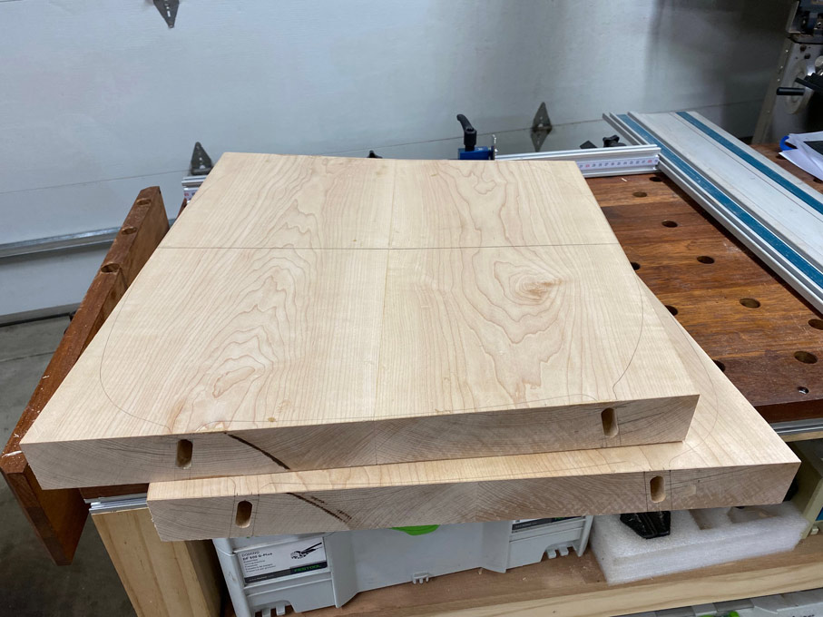
This is where we start - two seats completed on the upper side ...

Build33.jpg


Looking at the seat blanks from the side, it is apparent that they are 2" thick ...

Build34.jpg


... and they need to end up looking slim, like this ...

Build40.jpg


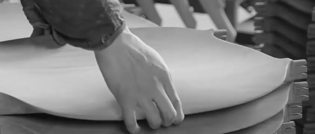
Clearly, there is a great deal of waste to remove from the sides. That is, not to thin the thickness, but to taper the sides to create the impression of thinness.

Here is another view, which better illustrates this ...

Build45.jpg


The MFT makes a good bench for carving ...

Build35.jpg


Lines are roughly pencilled on the seat and then the Arbortech is used to carve away as much waste as possible ..

Build36.jpg


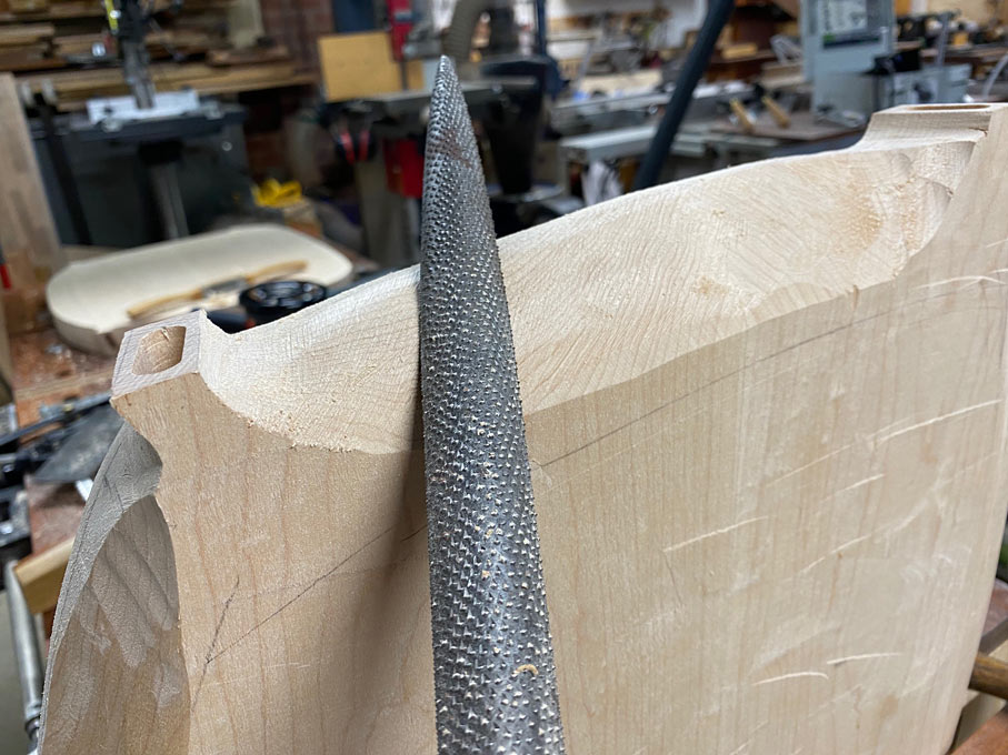
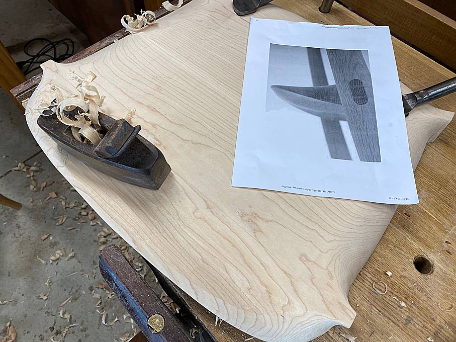
I relied on a Auriou 10-grain rasp to do most of the shaping ...

Build37.jpg


... until I was loaned the largest rasp I have ever seen. Large enough to cause most here rasp-envy. It says Nicholson on it, but it appeared larger than a Nicholson #50, and far, far coarser than the 11-grain it is advertised as having. Any ideas?

Build38.jpg


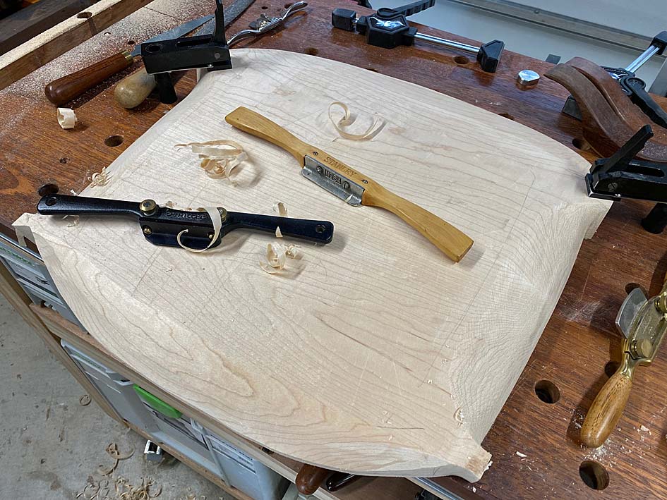
I moved between rasps and spokeshaves to shape and smooth the curves ..

Build39.jpg


To be frank, I worked without a specific plan other than to create fair curves - the curves almost decided what waste to remove, while I monitored the photos I had for reassurance.

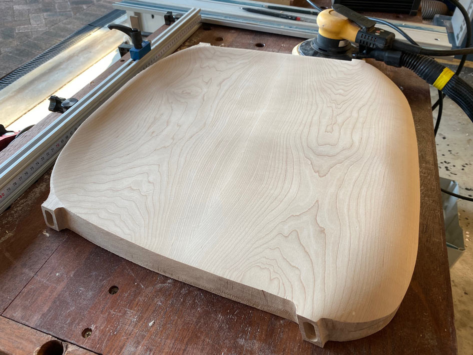
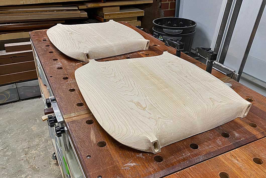
In the end, with everything sanded to 80-grit, this was the result. From the underside ...

Build41.jpg


The upper side, from the rear end ...

Build42.jpg


And side ...

Build43.jpg


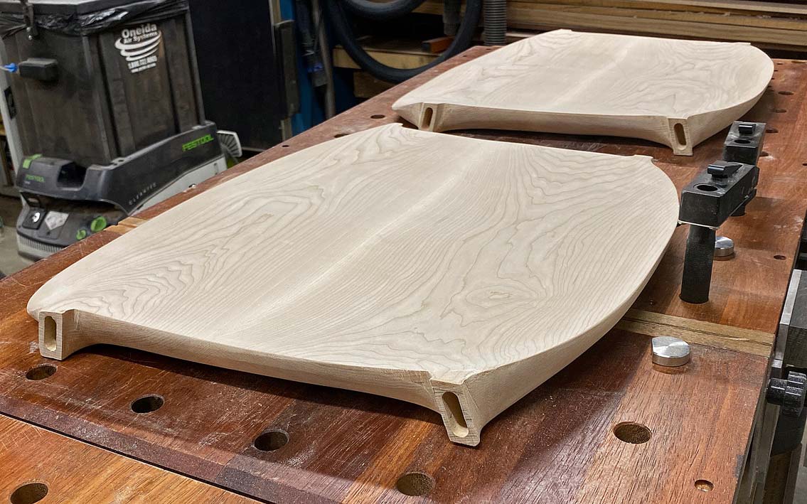
And one more photo, taken at an angle similar to the "slim line" view above ...

Build44.jpg


There is still work remaining in the seats: every time I look at the chair photos new details become apparent. So I shall get on with the legs, and return to fine-tune the seats later.

Regards from Perth

Derek
 
New Legs

Every time I sit down to write up the progress made I feel like apologising for how little there is to show for the efforts made. I have made this observation before - it is tough to copy from photos when there are no measurements to follow, but it is especially so when the piece is curved and changes shape from different angles. I keep finding new detail to add in, and it seems like a never ending carousel.

One example, the front underside of the seat is concave and not convex. I added this, but need to do more ...

L1.jpg


The seats need quite a bit more work, mainly refining details. For example, the sides need to be tapered more. For later.

For now I return to the legs.

I did make 8 legs when building Mark 1 of the chairs, but now I am about to re-make them completely. Why? Because the first set of legs were designed for a chair which was inspired by the DC 09 Chair, but now that I am attempting to get close to this design, the legs also need to be in keeping.

Step one was to create a template, and then mark out 8 legs. These were bandsawed close to the lines, and then cleaned up with spokeshaves ...

L2.jpg


The second time around is always easier, and marking out the mortises was much more efficient by measuring the front of the legs ...

L3.jpg


... and then dropping the verticals ...

L4.jpg


This is made possible by ensuring all sides were kept square when the leg blanks were made.

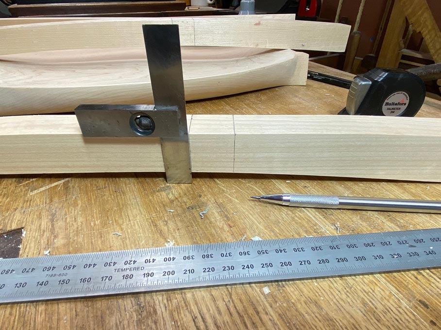
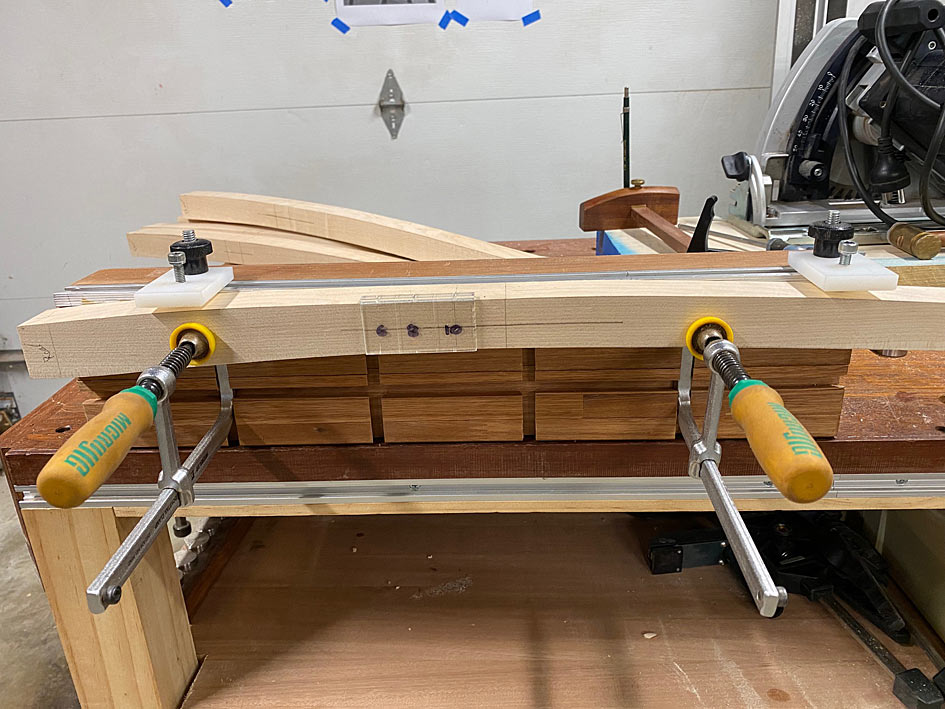
As before, the Domino was used to mortice the through tenons. The legs are clamped to a mortising fixture.

L5.jpg


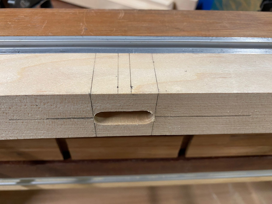
The mortises are 30mm long and 10mm wide, and through the 30mm thick legs. Since the Domino 500 can only rout to a depth of 28mm, it was done by working half way from each side.

The mortise needed to be marked very accurately, and to do this I used a marking jig I developed and wrote about recently ...

L7.jpg


The article is here: https://www.inthewoodshop.com/Powered Tools and Machinery/DominoDW500AsAMortiser.html

It was possible to be as accurate as this for both sides and all the legs ...

L6.jpg


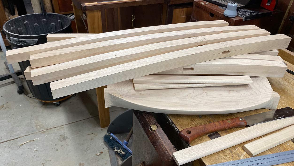
This ended with a pile of legs blanks plus mortises ..

L8.jpg


Early on in the build of Mark 1, I attempted to use a half-round bit on a router table to round the legs. This was a disaster as the Rock Maple blew up, leaving me with wet trousers. Looking back on this sad experience, I realised that I had literally bitten off more than I should have chewed. So I was determined to try again, but this time rout in stages, little-by-little ...

L9.jpg


The leg at the rear is one I attempted purely with spokeshaves. It was a miserable experience - Rock Maple is well named.

Here are 8 semi-finished legs. The corners have been rounded, but much of the leg is still square-ish owing to the tapered profile - the legs start at 35mm at the top, are 30mm by the mortise, and end at 22mm at the feet. Consequently, there is still a whole lot of shaping still to do.

L10.jpg


Look closely and you can see the flats on the sides.

There followed a lot of spokeshaving.

A progress shot of 4 completed legs and 4 incompleted legs ...

L13.jpg


"Completed" really means "done for now". There is constant refining. Slowly the square becomes less so, and then round, but with imperfections, and then eventually there are just fine tracks ...

L11.jpg
   

I must admit that it is so tempting to leave it like this, where fingers can caress the tool marks ...

L12.jpg
         

This would look better on a different style of chair, and the DC 09 is better suited to a sanded finish.

Here are two of the legs to gauge progress. Note the photo on the wall in the background for comparison (also recognise that the arm section of the legs has been left long at this stage)...

L14.jpg


L15.jpg


Until next time.

Regards from Perth

Derek
 
When I began this build, I looked at the legs of this chair and recognised that they were curved, tapered and oval. Well, oval at the top and round at the bottom ...

Chair2.jpg


I wasn't sure how to do this - the tapered oval shape. I just accepted that I would discover this as we went along.

I began by shaping the legs in profile and cut the mortises ...

L8.jpg


Then knocked off the corners with a round over bit. The leg at the rear was an attempt to do all with just spokeshaves - not great. The round over provides a helpful guide ...

L9.jpg


This left them rectangular with rounded corners. This weekend the rectangles became tapered ovals.

Working at the bench, holding the legs in a clamp ...

LL1.jpg


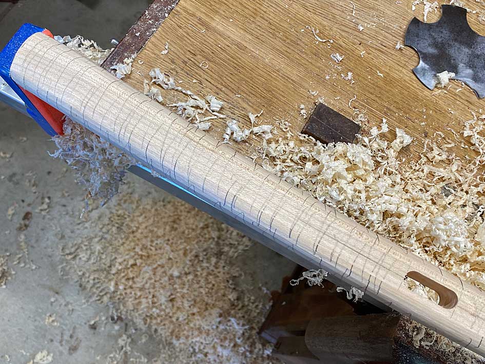
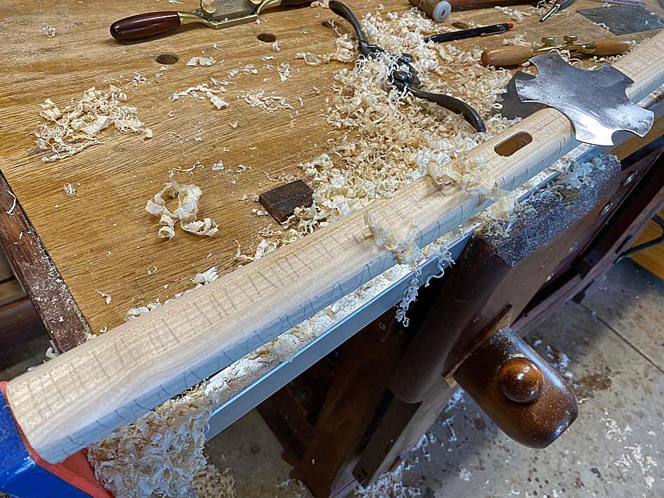
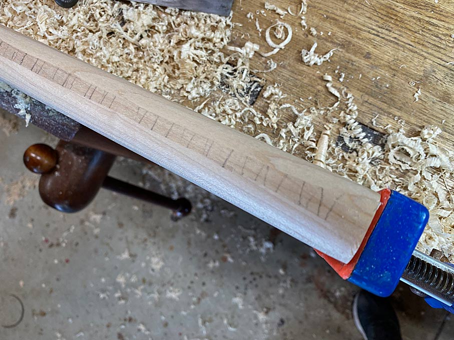
The first step was to cover the legs in pencil scribble. The purpose here is to make it easier to see where I am working. This Rock Maple is so light in colour and difficult to pick up details.

LL2.jpg


LL3.jpg


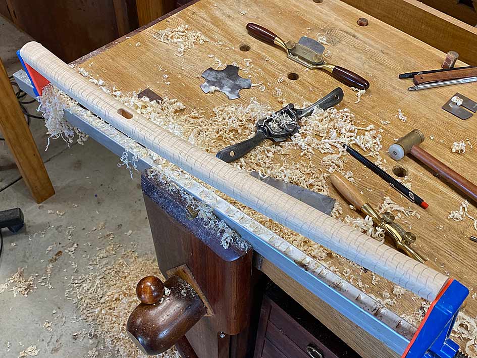
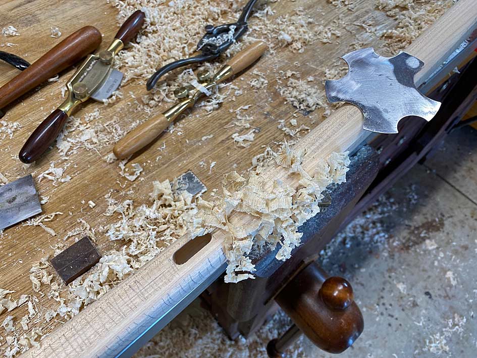
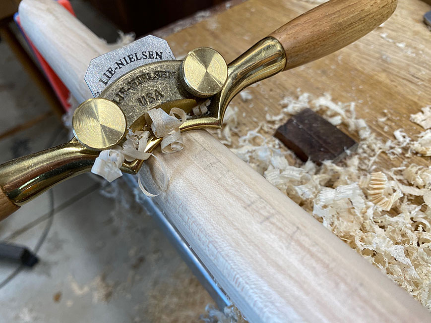
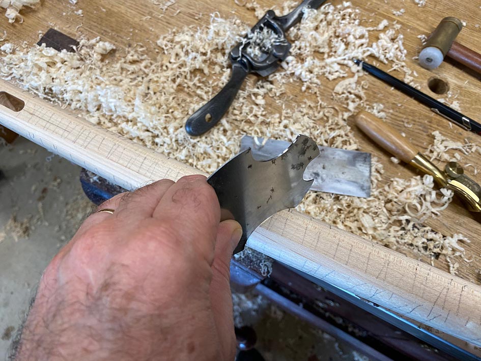
Some of the waste had already been removed by spokeshaves, but now the final shaping needed to take place. The tools used were a convex spokeshave and a set of convex scrapers - different sizes.

Once sharpened, the scraper make nice shavings ...

LL5.jpg


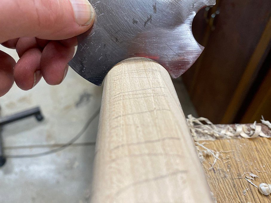
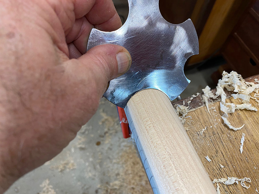
The scrapers also provided a template for the curves to be retained on the legs. The taper on the sides of the legs goes from 40mm at the top to 30mm at the mortice to 25mm at the feet. The edges (facing forward and rearward) is a uniform 30mm. So this meant that there was a single convex scraper for the edges and two scrapers for the sides.

This is the difference between a scraper and the leg ...

LL4.jpg


Running it along the leg reveals the low section through the centre ...

LL6.jpg


As you work down, so the curve increases, and the high spot gets smaller ...

LL7.jpg


The convex spokeshave helps out ...

LL8.jpg


Also, angling the scraper allows a wider cutter to follow the outline of a narrower section ...

LL9.jpg


Eventually, the scraper and the leg share the same profile ..

LL10.jpg


LL11.jpg


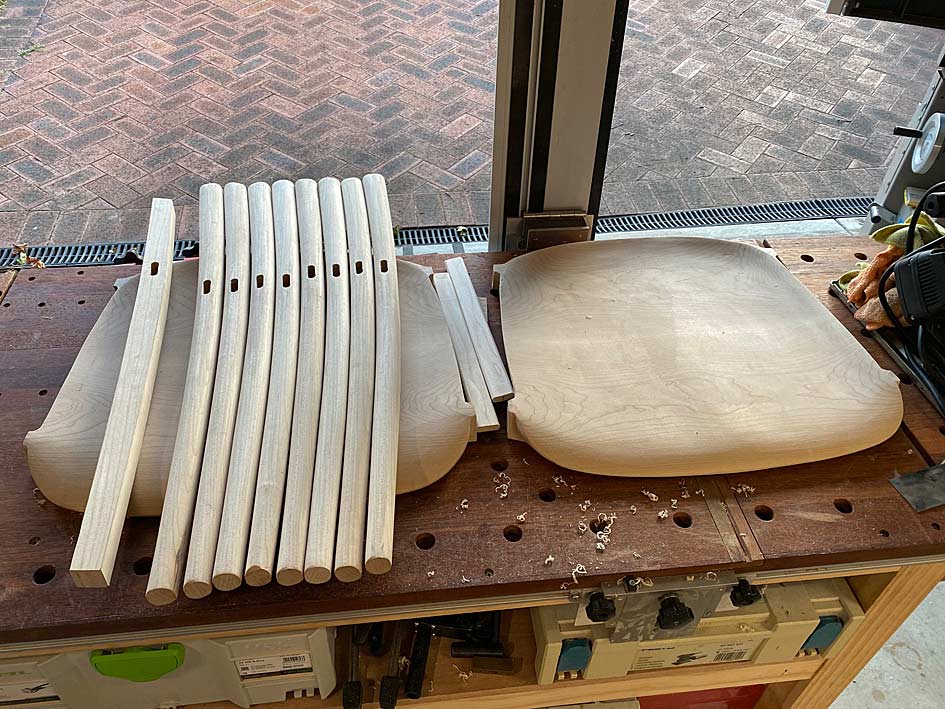
Lots of work on a very humid weekend. All legs completed now ...

LL12.jpg


Regards from Perth

Derek
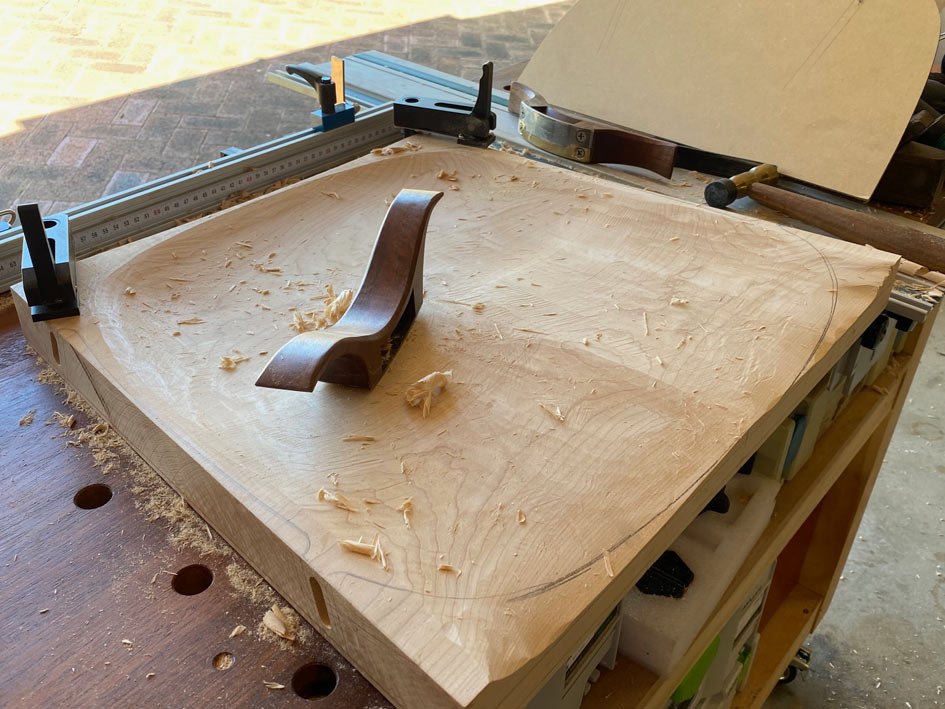
 
I must admit that this is an unusual build for me. I literally do not know what I am doing ... insofar as I have to keep returning to parts to refine and refine them. That is what is so time consuming. I don't always score high on being sensible, but I do on perseverance and being bloody minded!

Today was not a work day, and I ear-marked completing the seats. The upper side was 99% done, but the underside needed fine-tuning. I have two photos to guide the shaping ...

Seats1.jpg


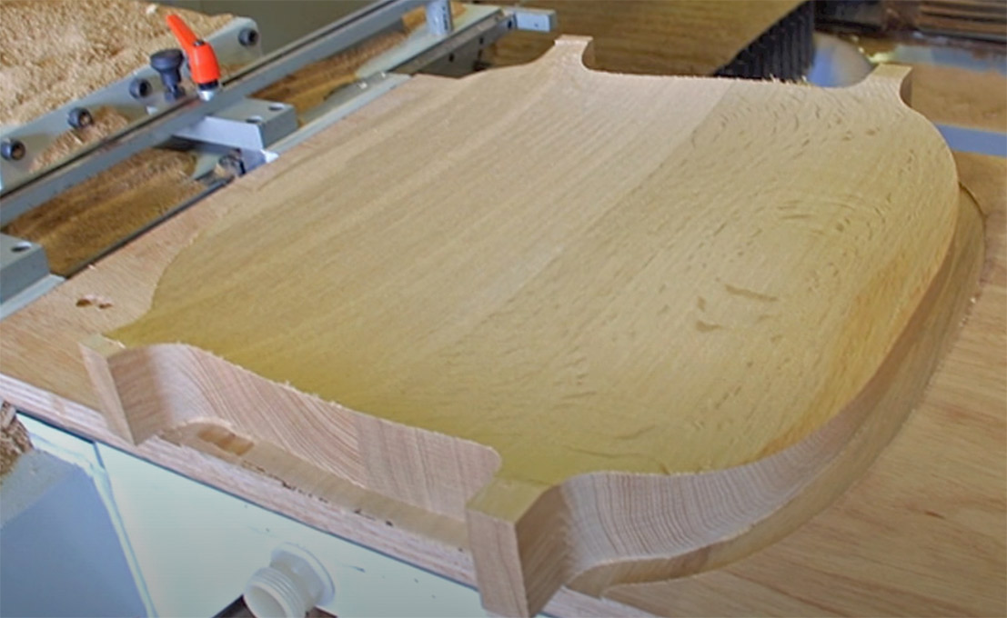
That one (above) is from the factory building the prototype. They screwed the legs to the seat, rather than use integrated tenons. This proved to be a great model in my case.

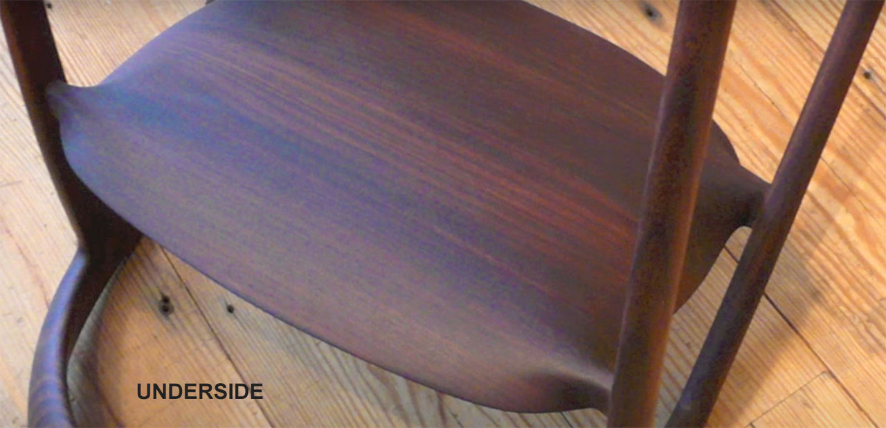
The second photo is a production chair seat taken from the underside. In particular, this shows the treatment of the smoothing of the tenons and their integration with the back ...

Seats2.jpg


Lastly, I keep returning to this photo of the chair, which shows how thin the seat looks from the side. Keeping in mind that the seats started out at 50mm, and were 40mm after the plan was cut out, a great deal of tapering was necessary to achieve this look ...

Build40.jpg


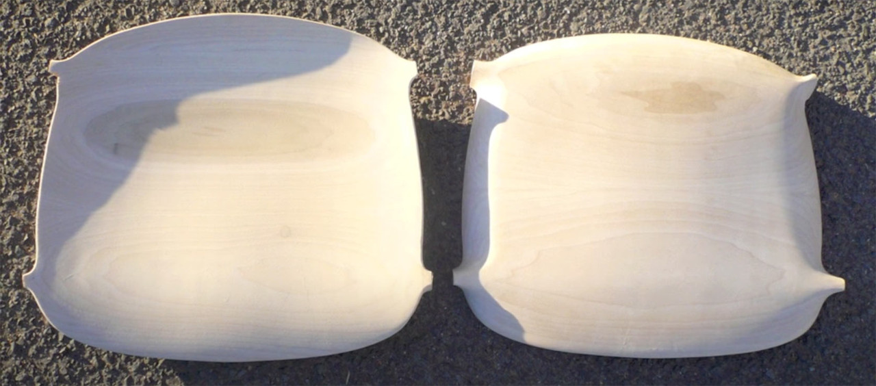
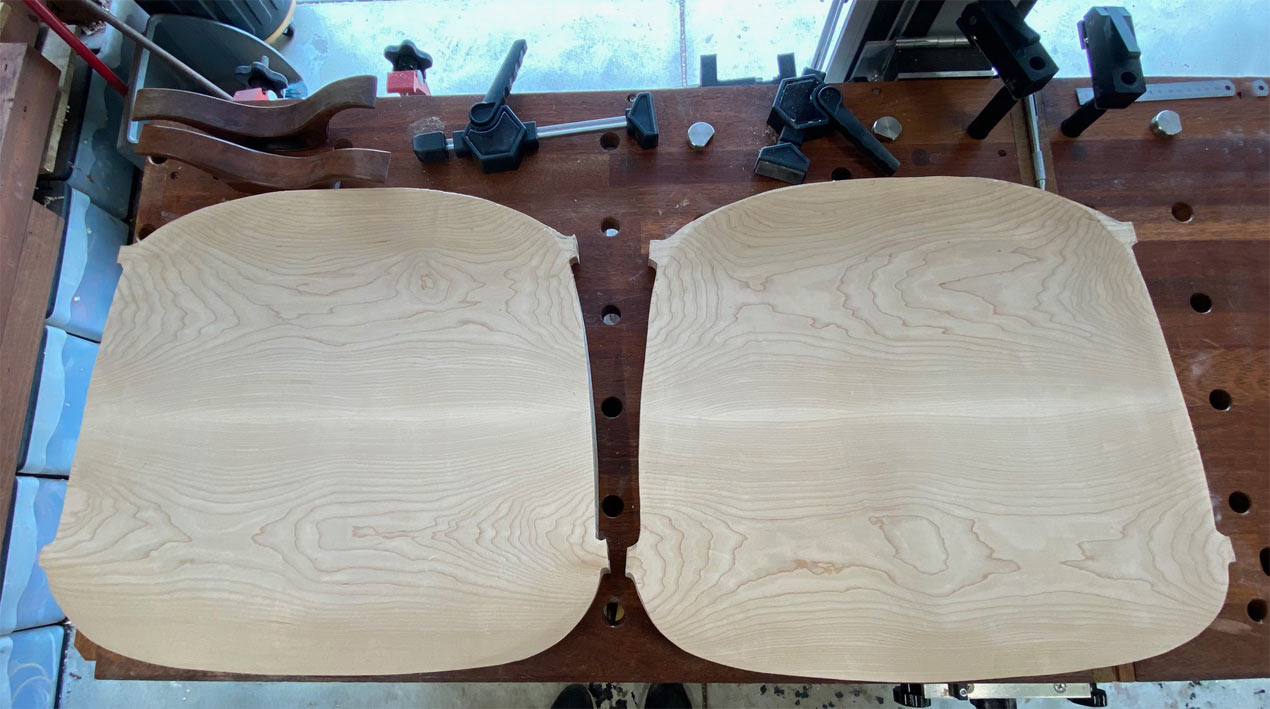
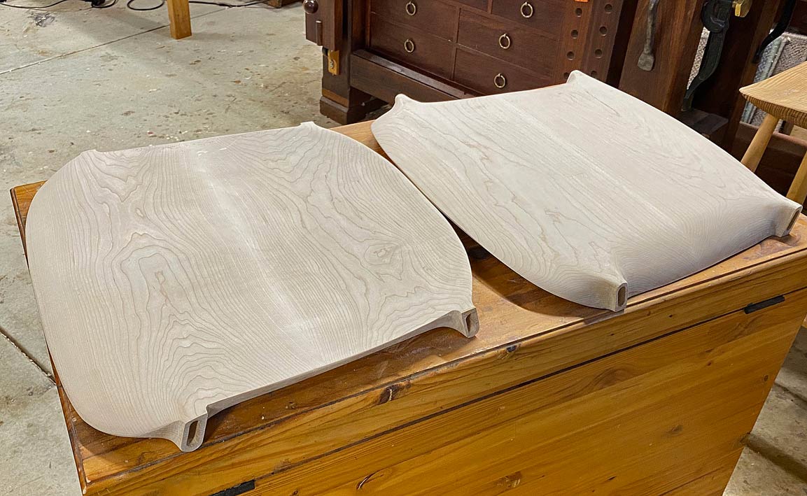
Here are the two completed seats. The seat on the left is face up, and the seat on the right is bottom up ...

Seat1.jpg


Regards from Perth

Derek
 
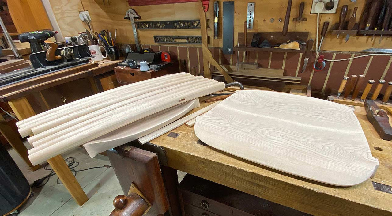
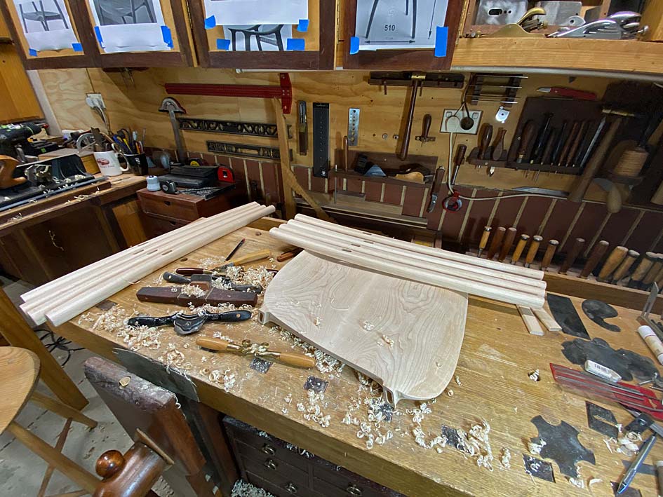
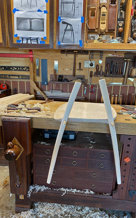
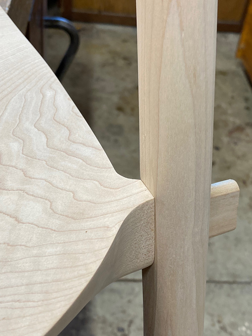
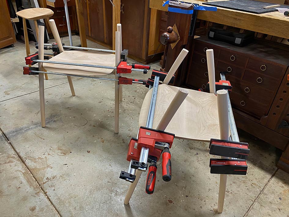
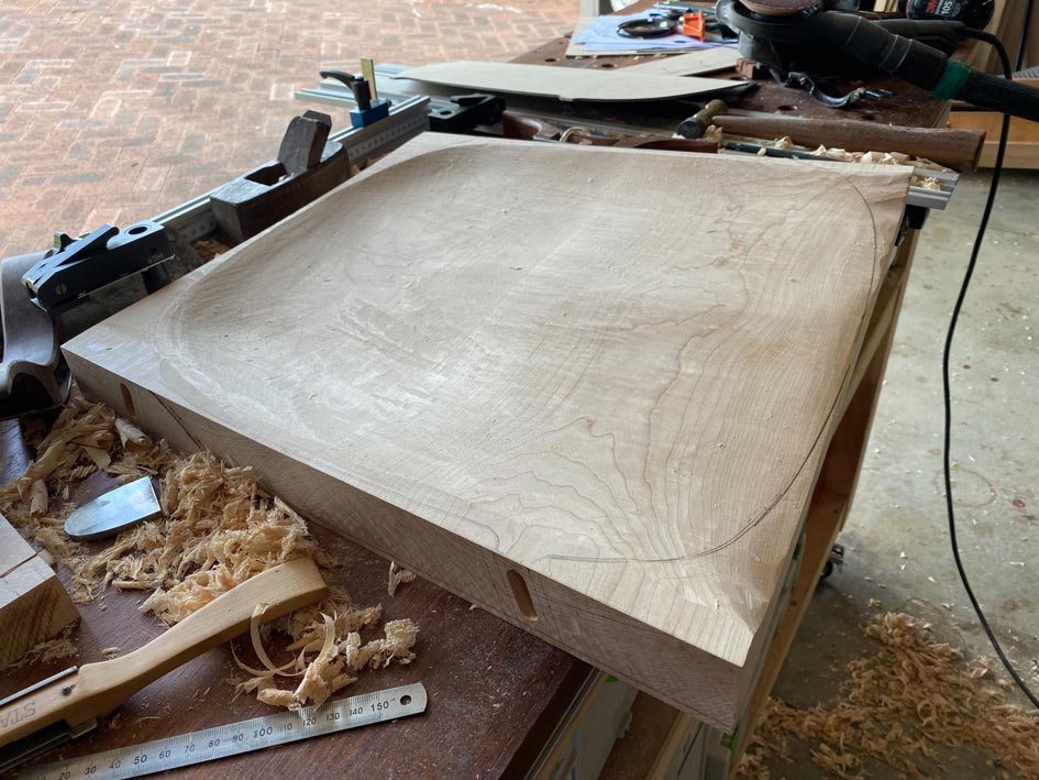
Today we reached the milestone I was patiently (okay, not so patiently) waiting for - glueing up the legs and seats. To get to this stage, however, required matching the mortices with the loose tenons, matching the loose tenons with the leg mortices, cutting slots for the wedges (into the tenons), and shaping the tenon mortise to fit the legs.

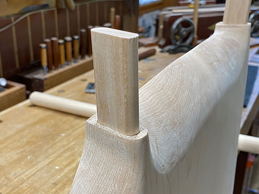
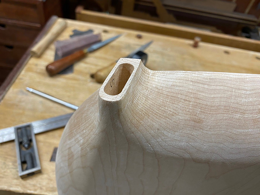
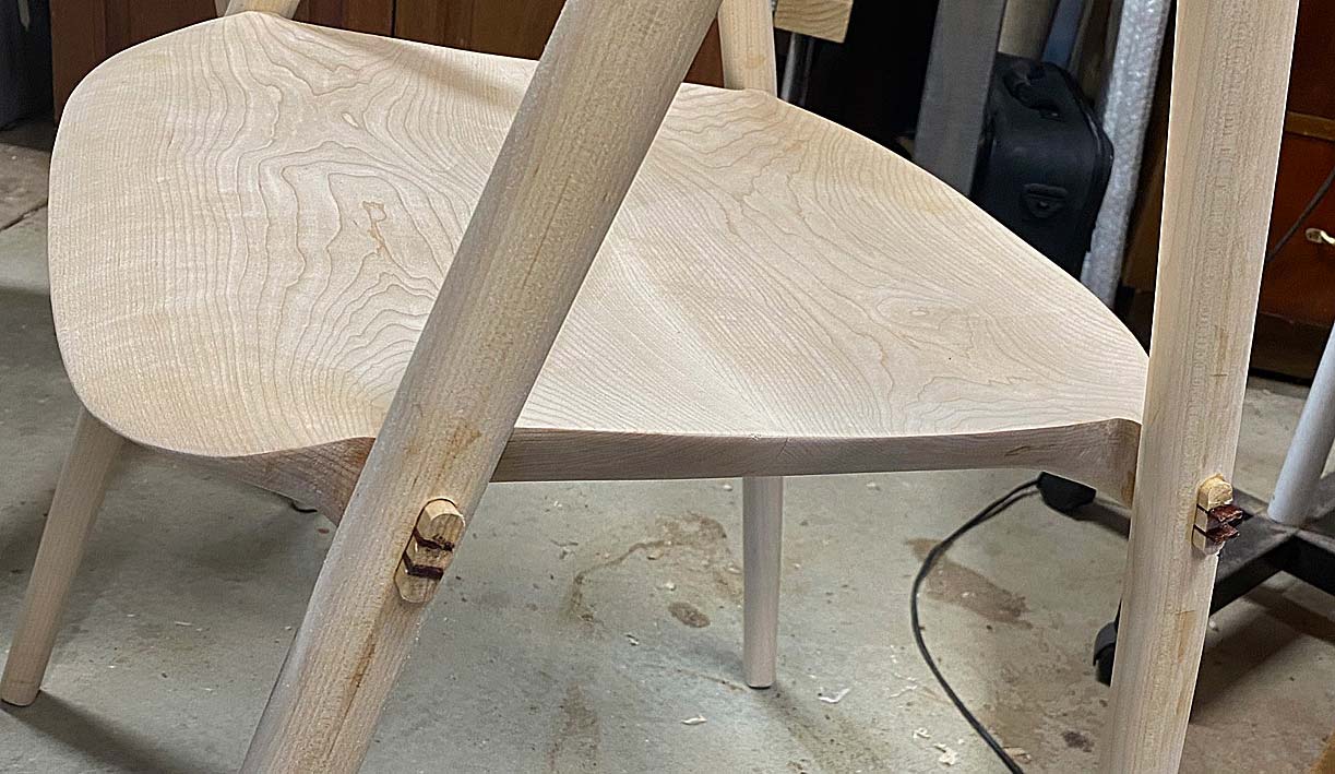
Let's start with the obvious. This is how the tenon and the tenon mortise will end up looking ...

T2a.jpg


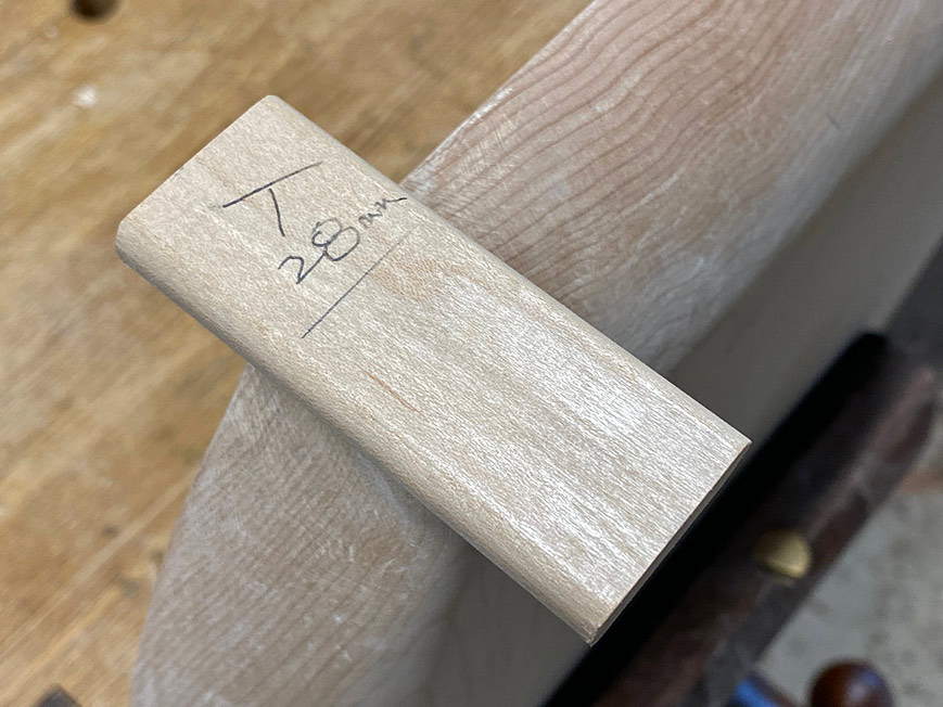
The loose tenon is 30mm wide and 10mm thick. It extends 28mm into the tenon mortise ...

T3a.jpg


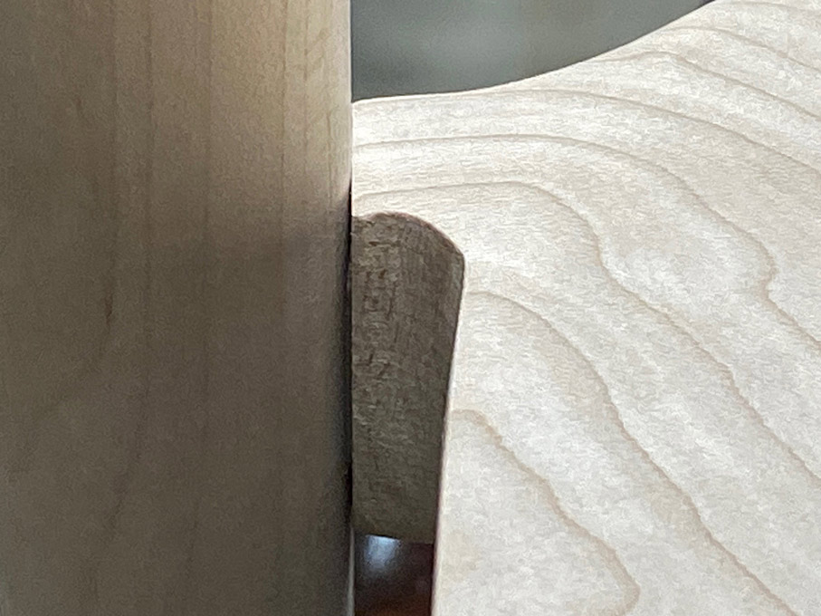
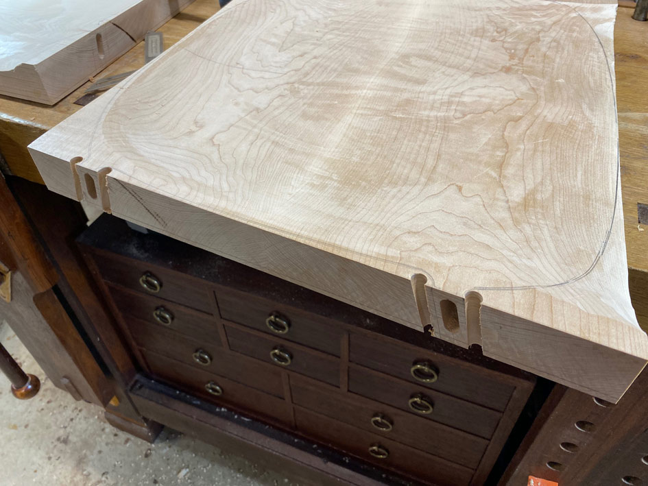
This all looks rather neat, but it was the end result of further shaping to fit the legs with the seat. The issue was that the seat mortices were chunky ...

Seat1.jpg


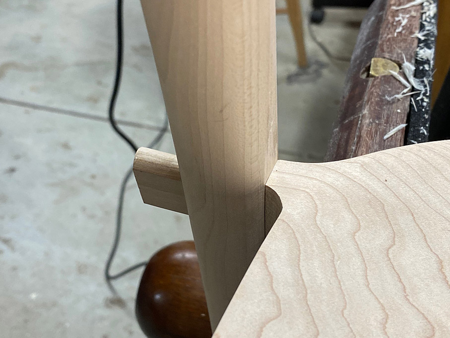
When joined, this was the fit ...

T4a.jpg


T5a.jpg


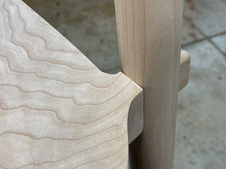
Two steps were involved. Firstly, the tenon mortise was reshaped to be thinner at the face (this involved removal of waste at the top edge and not the sides, which is needed support for the loose tenon) ...

T6a.jpg


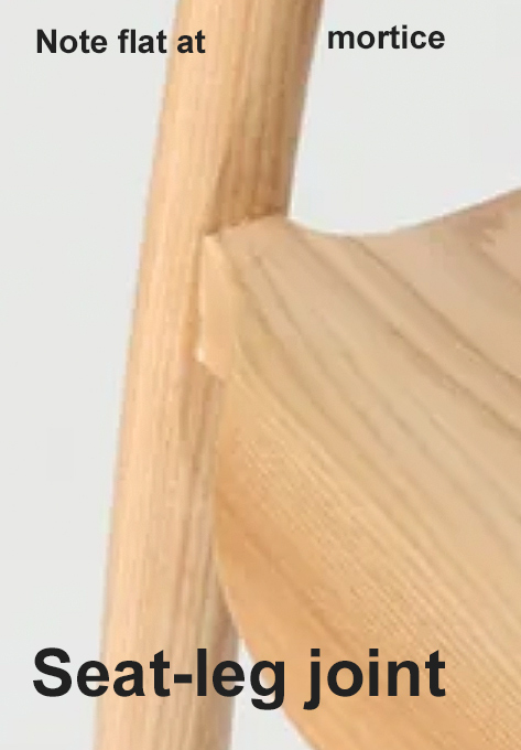
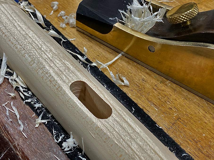
Secondly, the face of the leg mortise was planed flat to match the face of the seat mortise ...

T7a.jpg


This is how the original chair was fitted - photo I posted early on ...

Seats3.jpg


This is the result ...

T8a.jpg


T9a.jpg


All the parts fitted, but not yet glued up ...

T10a.jpg


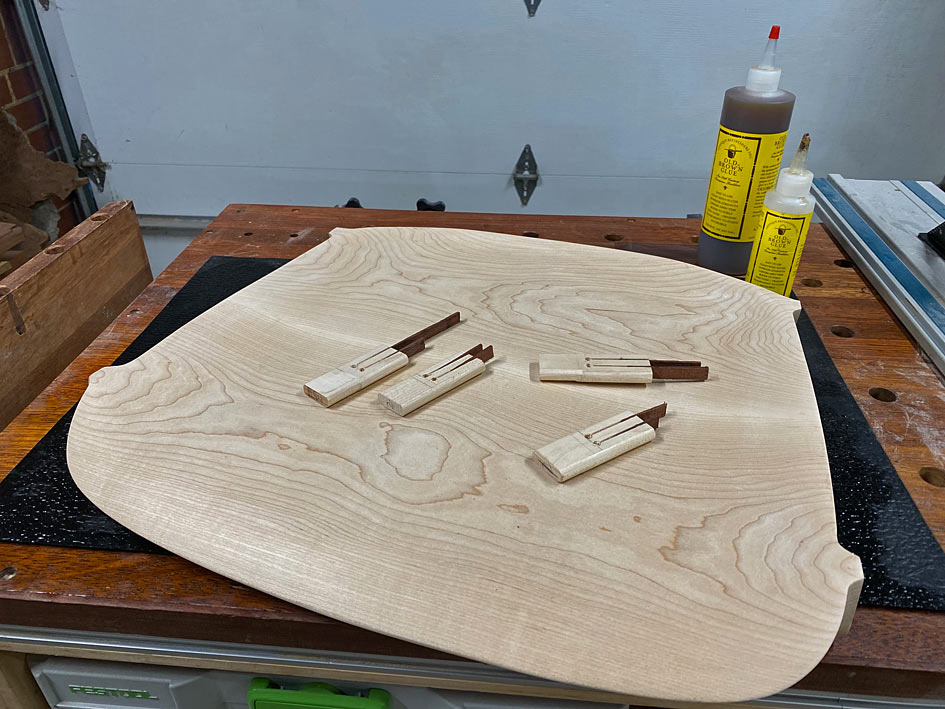
Loose tenons slotted for wedges, along with the wedges. Glue of choice: Old Brown hide glue. Why? Because at some stage in the future, hopefully many years from now, it is likely that the joinery will need to be re-glued.

T11a.jpg


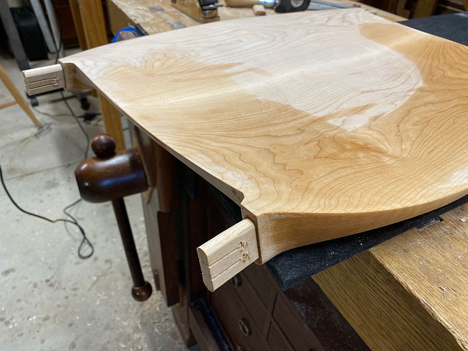
The seat tenons are glued first and the glue allowed to dry (they are a bit long here, and were cut shorter before the legs were attached) ...

T12.jpg


And a last photo of the final glue up. It will remain so for 24 hours.

T13.jpg


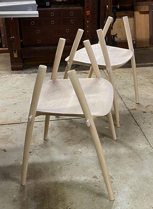
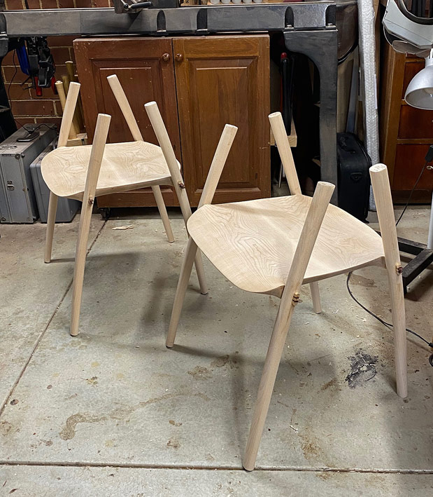
Starting to look like chairs!  ;)

Regards from Perth

Derek
 
I will forever be envious of both your skills and patience!  Can't wait for the next installment of this build.

Peter
 
A note about wedges

This is a cross post from the Australian forum, where I was asked for more information about the wedged through tenons.

I am not sure if the photo provided must detail, but the wedges are tapers, but also long and skinny ...

T11a.jpg


They both fill the slot - which is full of glue - and create a wedging action, firmly pushing the tenon edges against the glued insides of the mortise. The mortises, both in the seat and legs was 30mm long. Most were exact, some of the legs were a little under a mm long. A little filing for all to create this tiny gap - it does not have to be more. The glue is enough and the wedges are security. Interestingly, this appears to be the same in the original chair, with the exception that they added a chamfer for the end of the wedge. I've never seen this before (but understand the reason) ..

Chair-seat5.jpg


In addition to the wedged legs (I am trusting that the small amount of taper inside the mortises will add an extra layer of solidness), the arm/back structure adds stiffness and resists the legs wracking/moving. It is akin to triangulation of the construction (not really triangles, of course).

I have removed the clamps and the structure is really stiff already - I will wait until Lynndy is out of the way to take some photos. She-Who-Must-Be-Obeyed is keeping a steely eye on my "taking it easy" today!  [Explanation: I was in hospital yesterday for an op on my left torn patella]

Later:

I snuck into the workshop to unclamp the glue up. Lynndy caught me! But she then asked to sit on one of the chairs (sans the arms and back). She did so gently, and then with all her weight (55Kg). The seats did not even sigh, and nothing moved. She proclaimed the seat very comfortable. Yay!

Tenons and wedges yet to be cut and levelled ...

T15.jpg


T14.jpg


Regards from Perth

Derek
 
Beginning the arms and back

The legs and seats are done and it is time to move to the arms and backs. Once again, the chair to provide a context of where we are headed ...

Chair2.jpg


I was fortunate to find a few photos on the Web showing the development of the arms/back, which provided some insight into how to construct this ...

Seats4.jpg


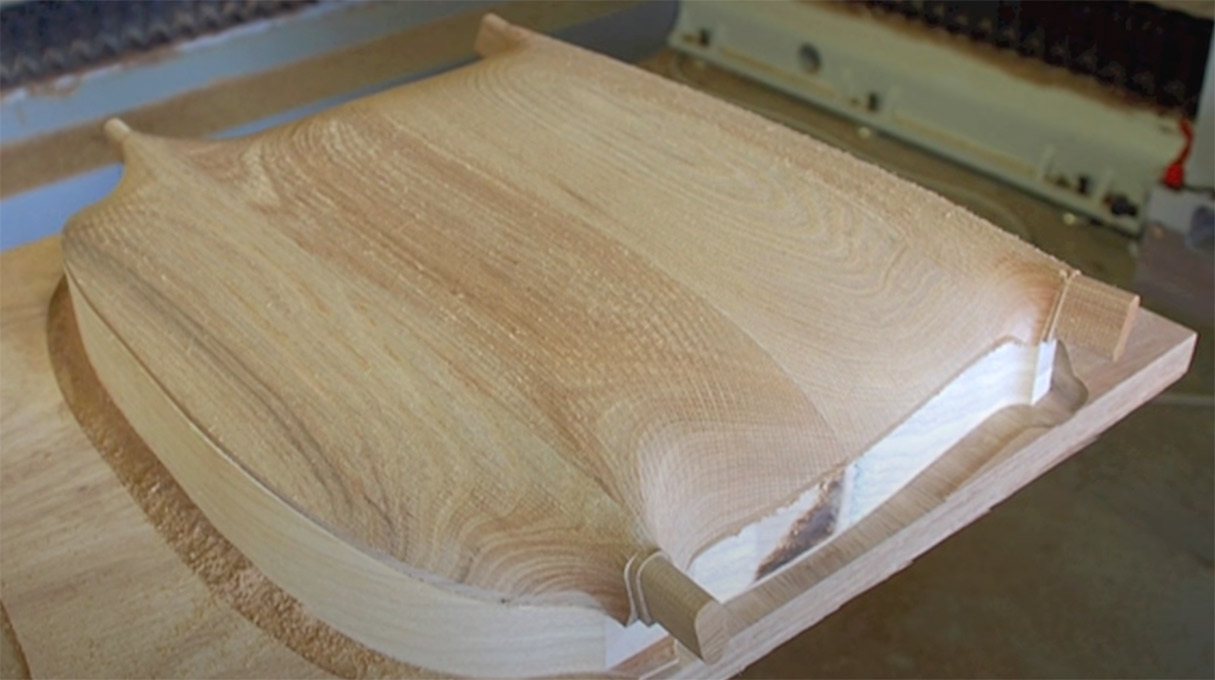
The construction sequence that was really helpful was this (note these are from the underneath) ...

Arms1.jpg


While this makes it all appear accessible, my experience building a Hand Wegner chair prepared me for the large chunks that make up the two arms and the back ...

TheChairShapingArmsBackPart1_html_m11f0c459.jpg


Giant slabs and lots of carving (since, unlike the factory, I do not have a CNC machine) ...

TheChairShapingArmsBackPart1_html_m2b87da0c.jpg


But look at the first photo in that sequence - the back is angled into the arms. Wonderful - less to carve!

Arms2.jpg


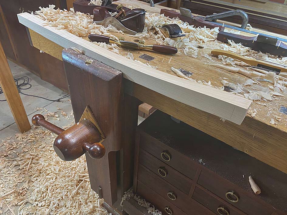
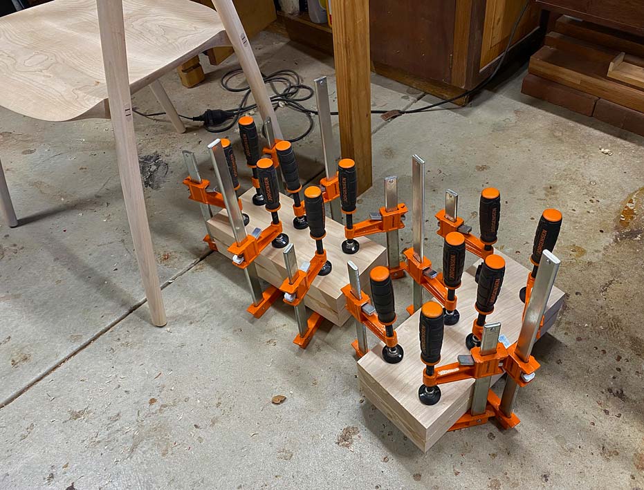
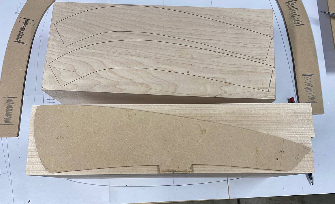
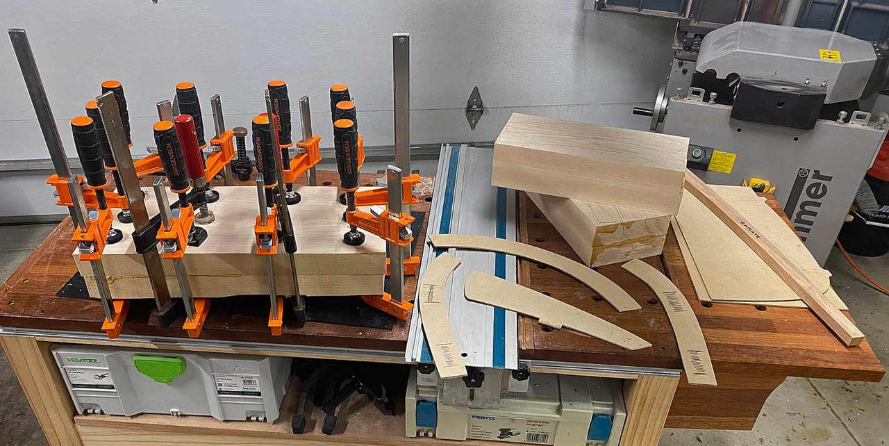
The arms need to be shaped from blocks 90mm high, so I got busy laminating ...

Arms7.jpg


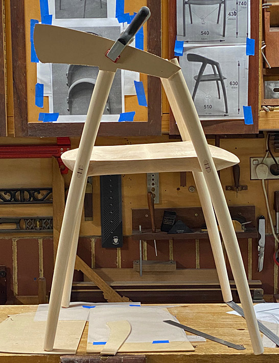
And while this was drying, time was spent on getting the profile for the side of the arms ...

Arms3.jpg


There's a photo on the wall behind against which to compare. Also, a first look at the completed through tenons.

That's the easy stuff. Time to design the arm and back profiles.

We start with a seat ...

Arms8.jpg


... to use to frame around ...

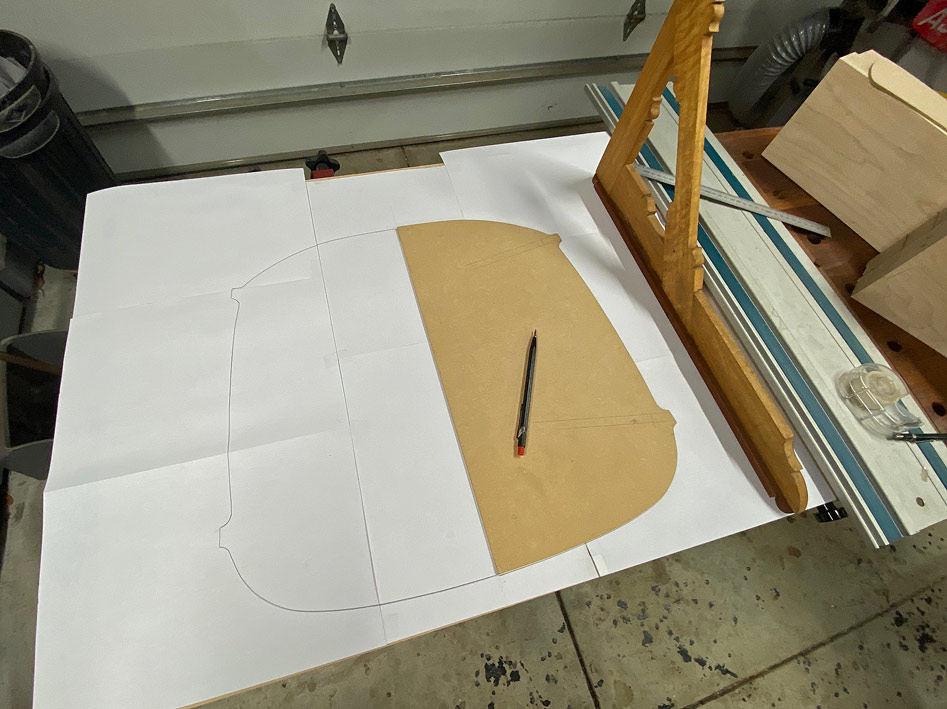
Arms9.jpg


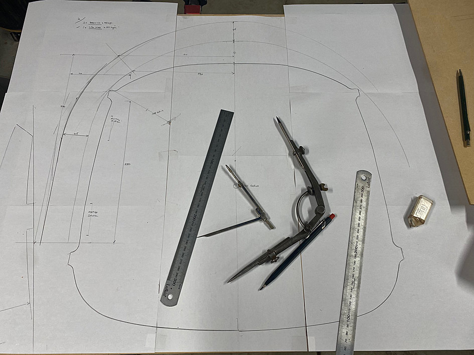
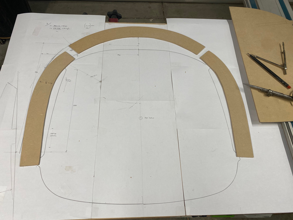
After much back-and-fro drawing, rubbing out, re-drawing, and transfering to MDF for templates ...

Arms10.jpg


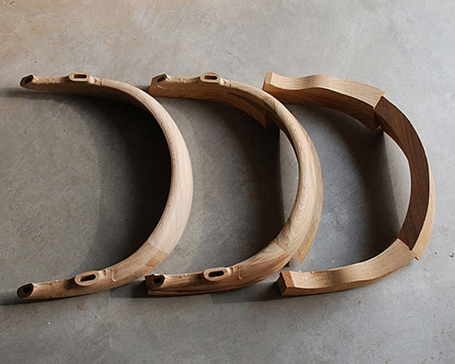
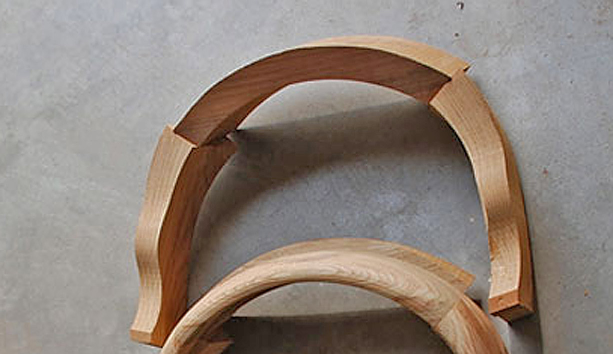
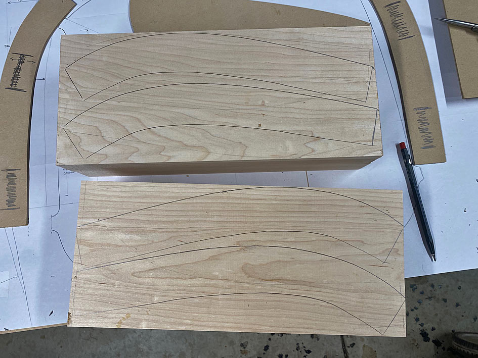
Each of the blocks (seen beng glued up earlier) create four arm blanks ...

Arms11.jpg


Here is the side elevation ...

Arms12.jpg


Wood for the backs came from sawing up this 3m long board ...

Arms13.jpg


And, for now, the backs are laminated and drying alongside the other blanks and templates ..

Arms14.jpg


Tomorrow I shall begin cutting it all up, and joining pieces together.

A question for all is how you might connect/join the arms with the legs? Note that the back will be joined angled to the sides, as per the photo.

Regards from Perth

Derek
 
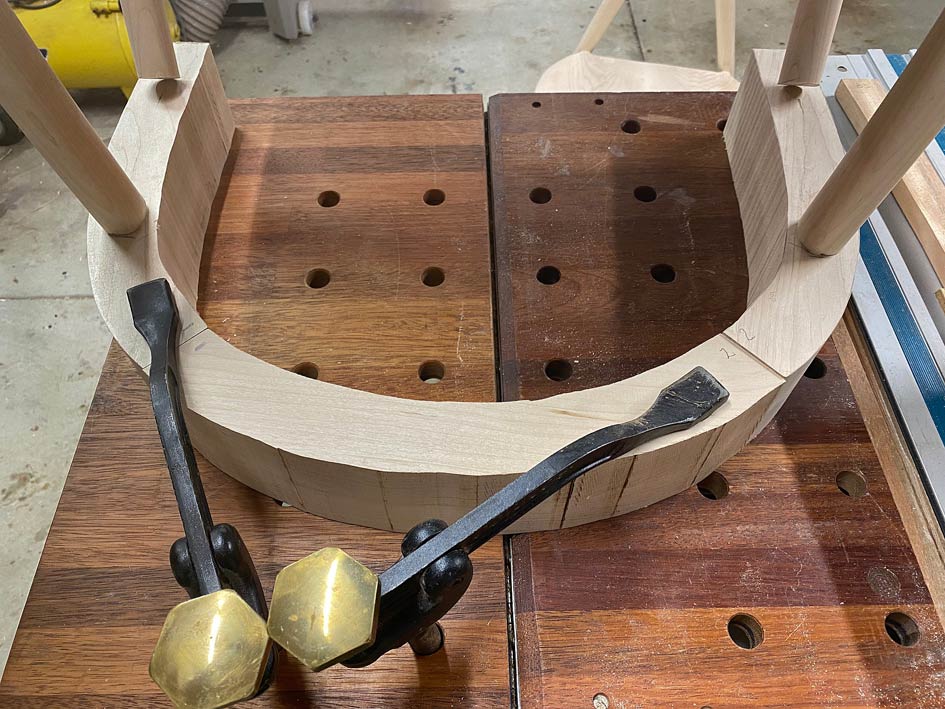
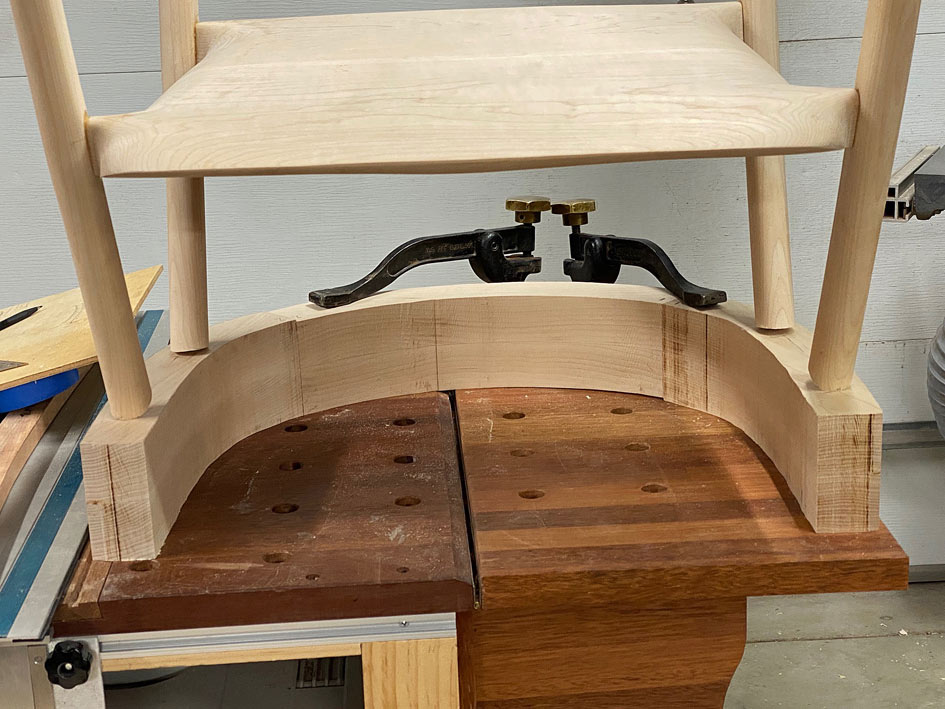
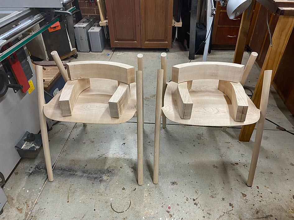
More of the arm jigsaw

Here is the work done today, which was preparing the arms before shaping. Critical work, and the day went well. This was mainly due to working methodically. Looking back it all seemed so logical and straightforward, but it didn't feel this way before hand.

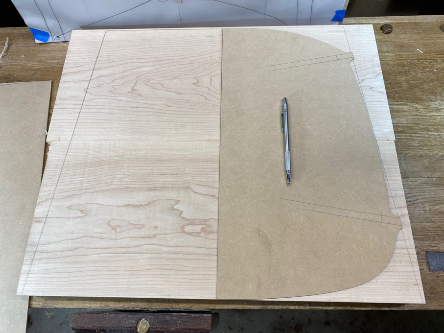
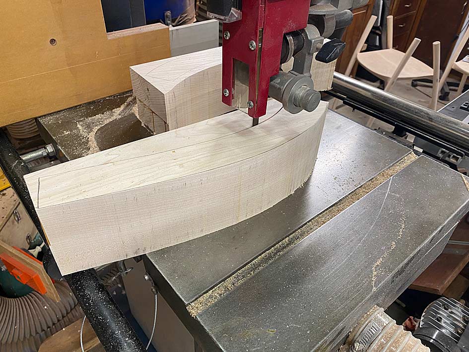
The first task was to bandsaw all the blocks of wood into shape, having outlined the parts with the templates.


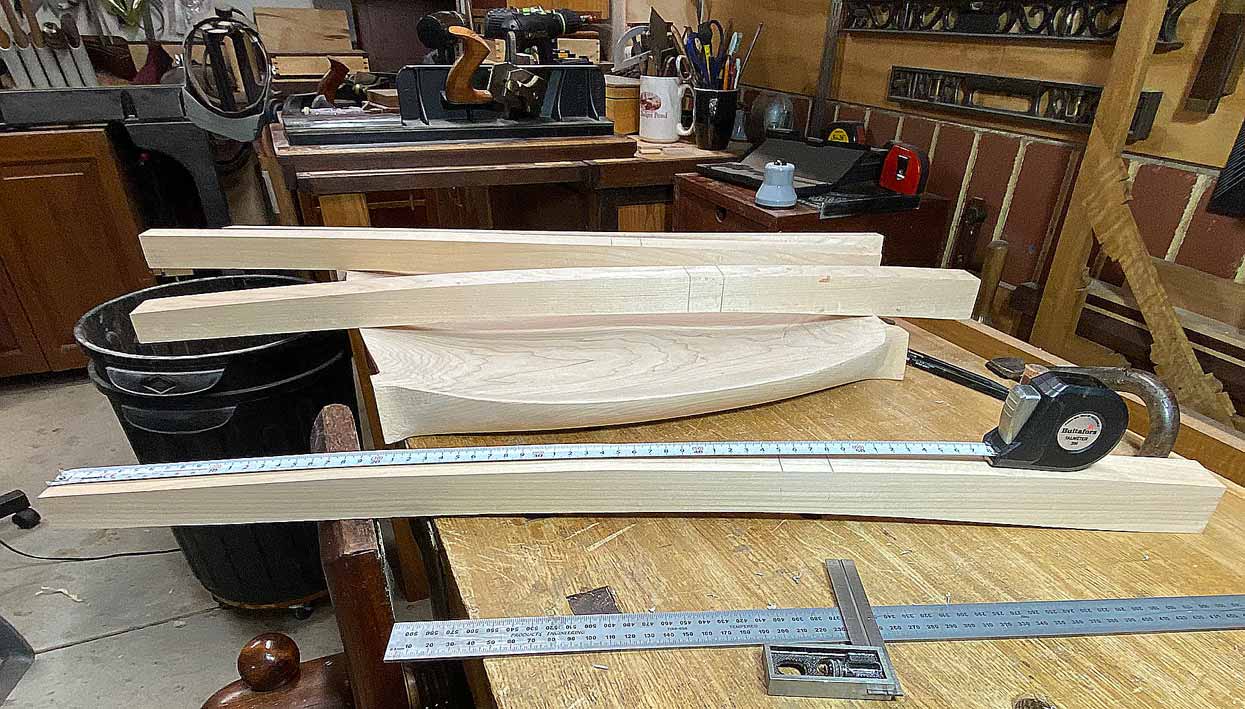
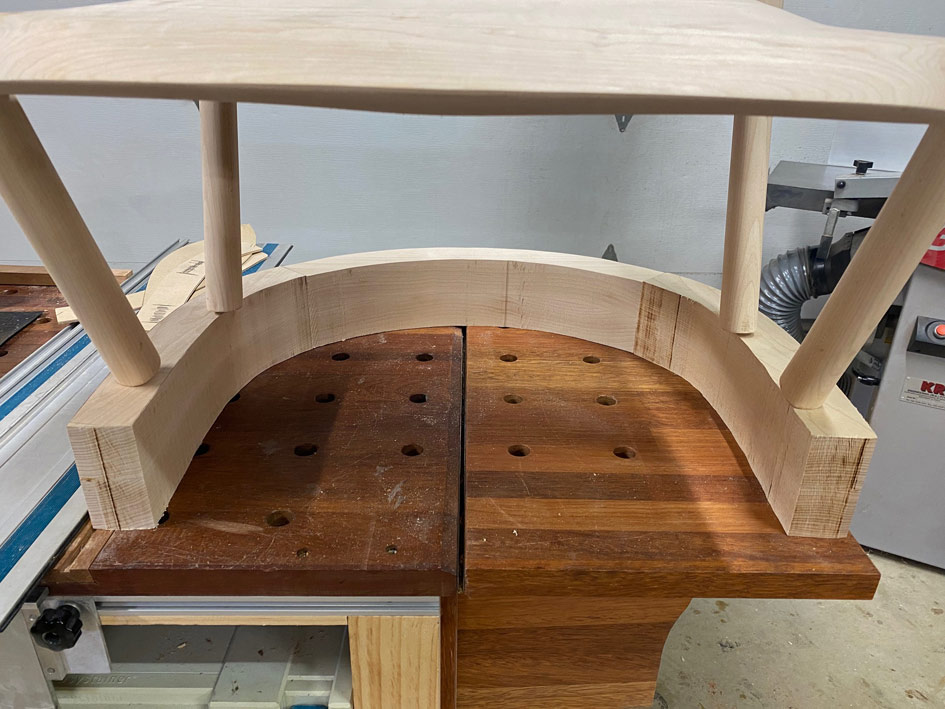
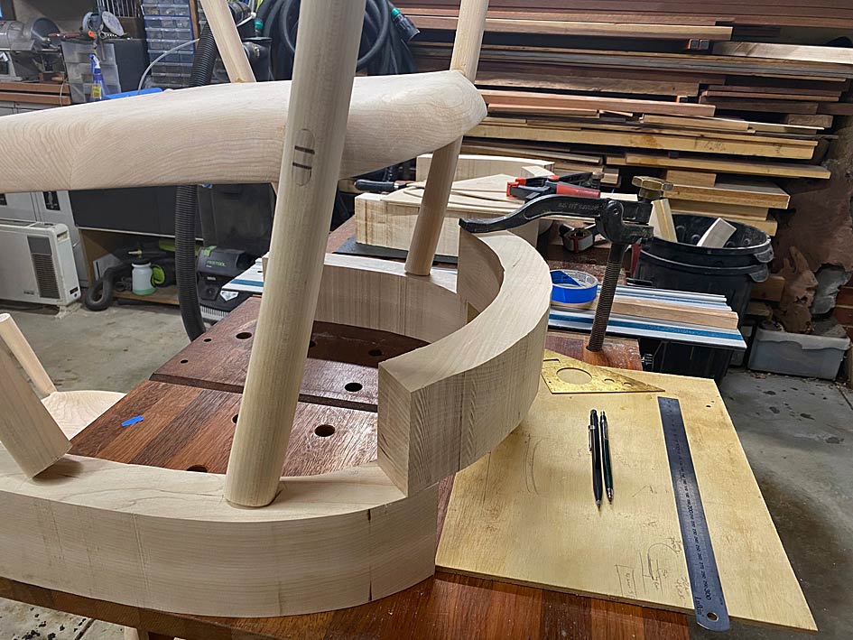
Lining up the arm parts for two chairs, three for each ...


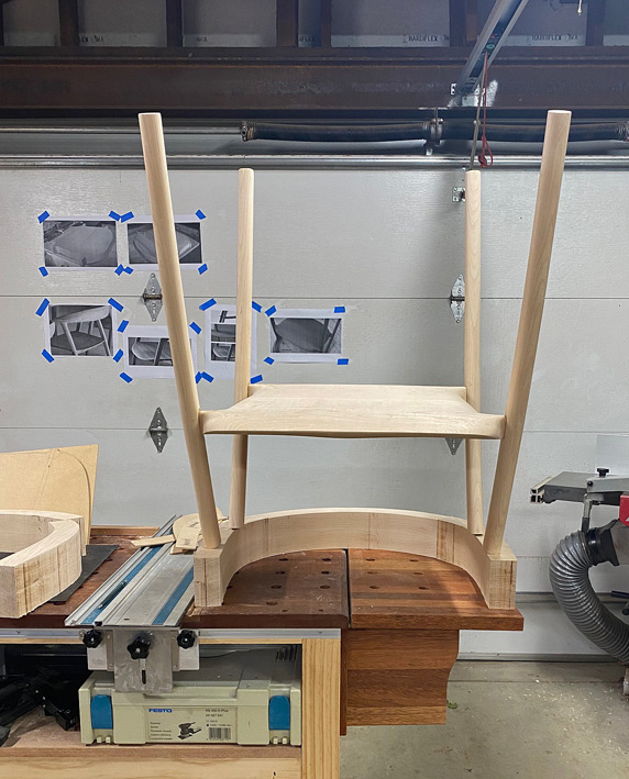
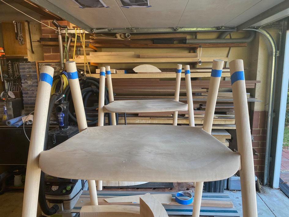
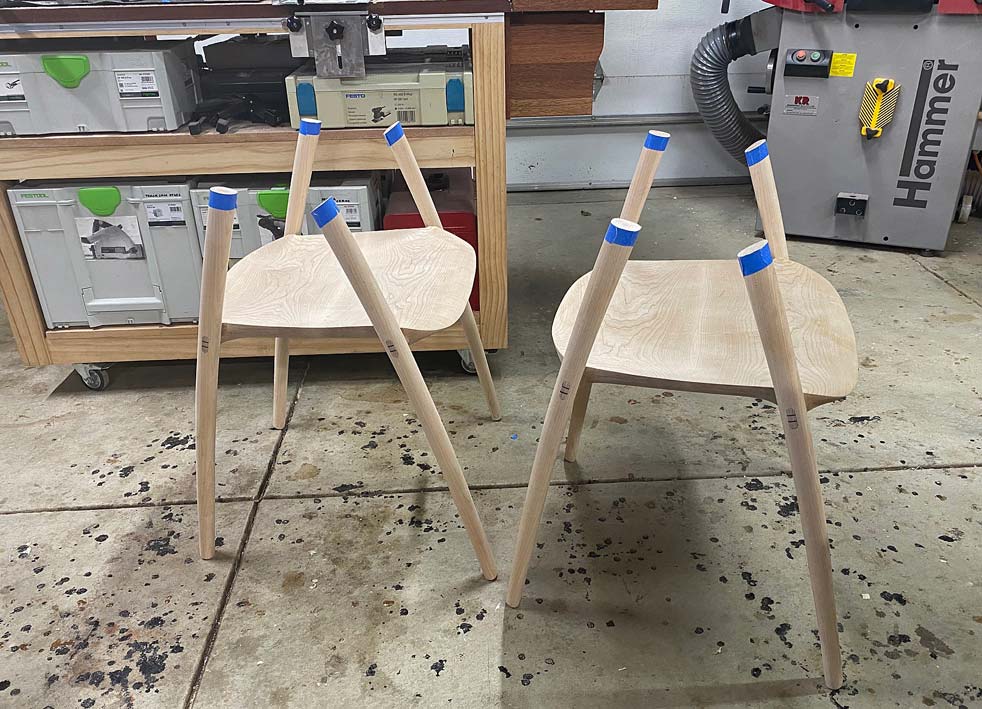
At first I thought I would clamp them together and balance the lot on top of each chair ... no, that would be silly! :)  The chairs were turned upside down on the arms ...


This revealed that the spread of the arms was a little too wide. The arm supports need to be centred on the arm rests ...


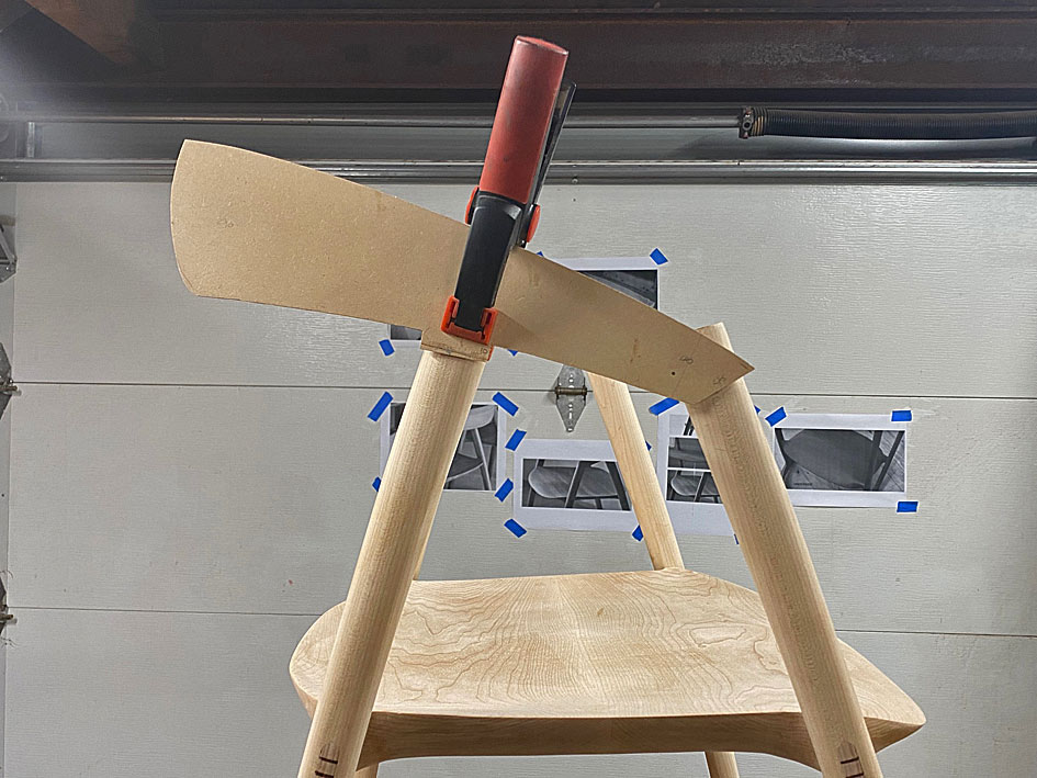
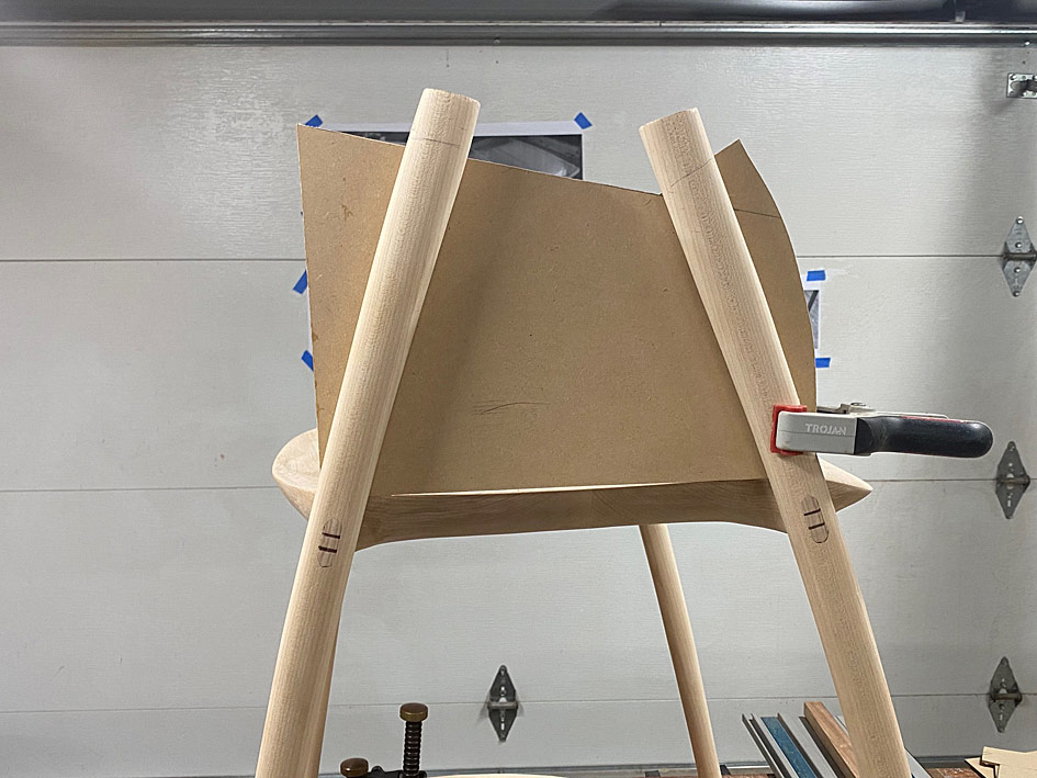
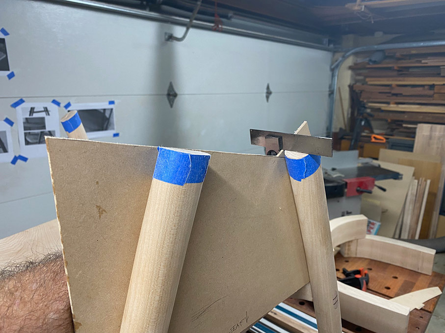
Before adjusting this, the next stage needed to be to cut the arm supports to length. To do this, first the template for the arm elevation was positioned ...


... and then a template was made to position this ...


This allowed all the arms supports to be marked on both sides ..


.. and marked with blue tape ...


The excess is sawn away ...


The template also enables the accuracy of the saw cuts to be checked, and for square. This will need to be fine tuned later, but good for now ...


The underside of the arms are marked so the positions on each will be the same, and the overhang at the rear was roughly calculated. Again, this will be adjusted after the arms parts are joined.

Now the top rail can be positioned for sizing ..


It is marked for sawing ...


Aligned on the slider ...


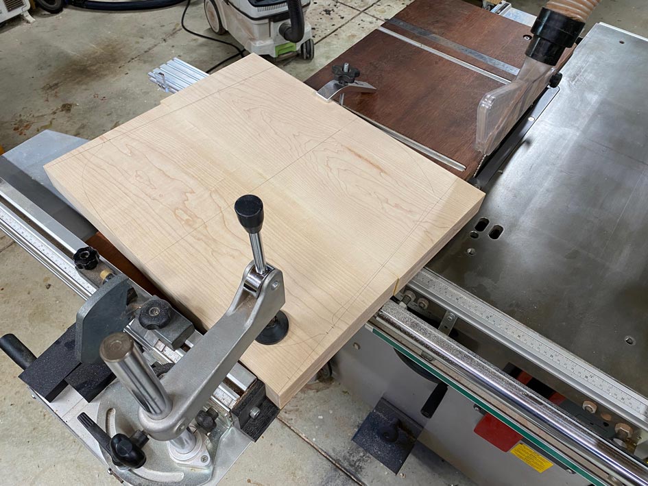
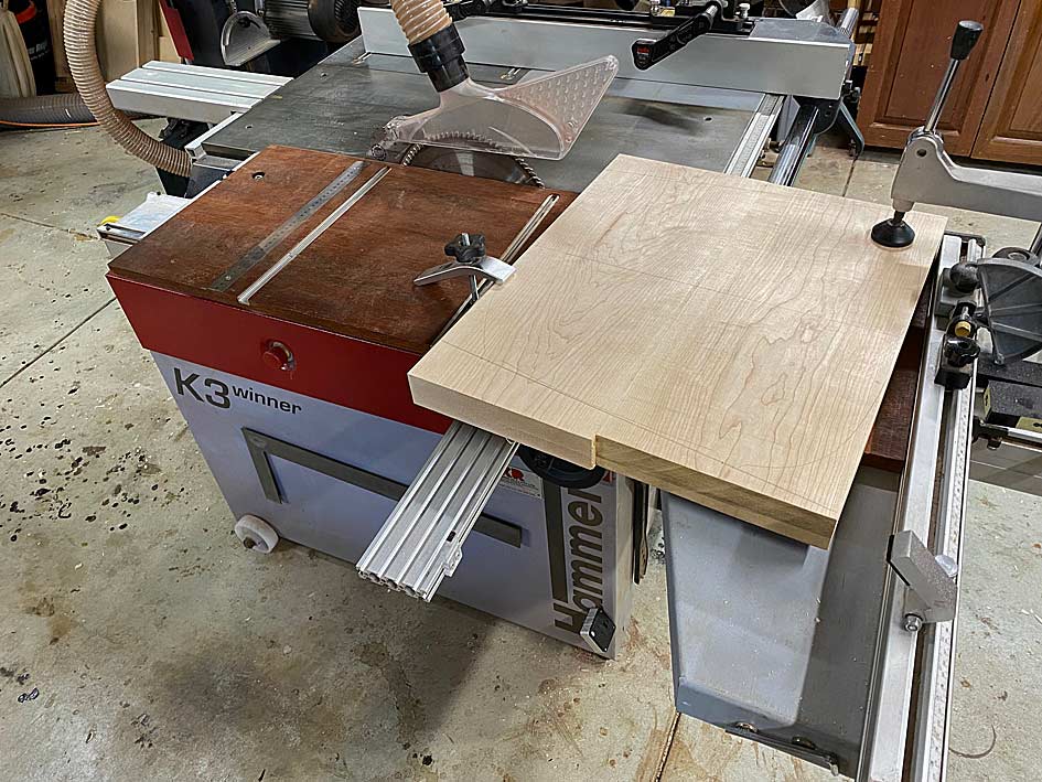
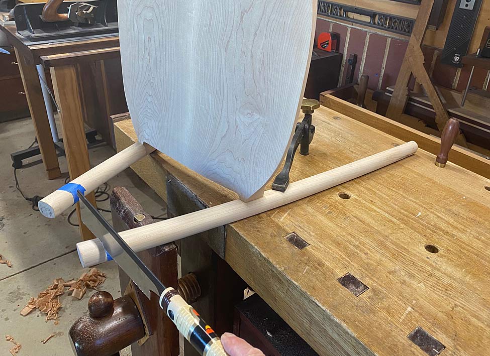
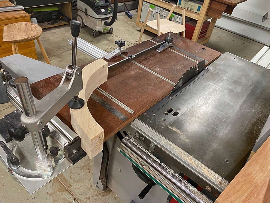
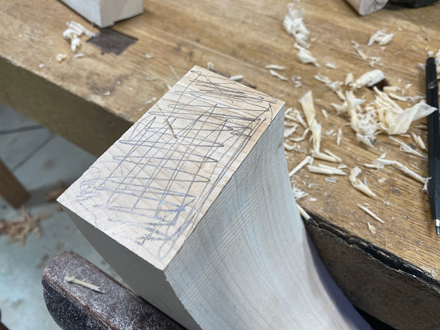
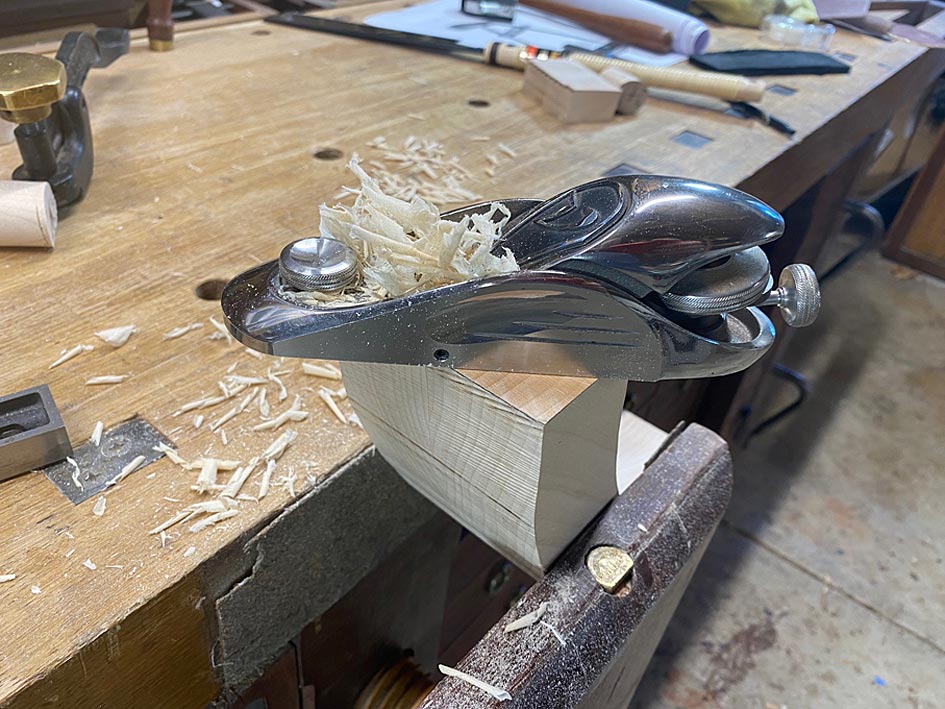
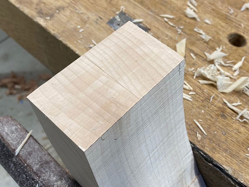
All the ends of the arms are squared this way, however the saw has a maximum cut height of 75mm and these parts are 90mm. This leaves 15mm to saw away with a hand saw, and then clean up with a block plane. This clean up is important as it is also jointing for the parts to fit together gap-free ...


The arm parts are ready to fit together ...


And all done for the day ...


Regards from Perth

Derek
 
Back
Top