DIY MFT using the LR32 kit

elekes.adam

Member
Joined
Jan 13, 2020
Messages
15
Hello Folks

I am a total newbie when it comes to the MFT. However, last week I bought the LR32 kit, so I thought it would be a nice test job to make a small MFT slab for later use.

So here is my rather simple approach to make my own MultiFunction Table.

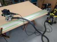
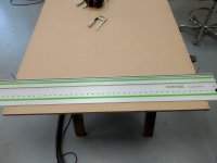
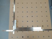
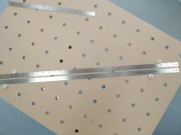
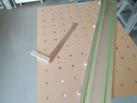
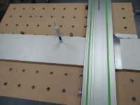
I started with a sheet of 18 mm MDF.
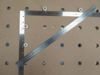
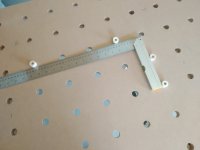
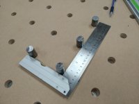
I quickly made three fresh, square-to-each-other edges.
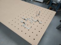
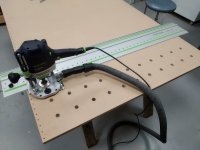
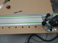
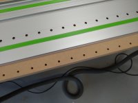
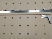
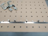
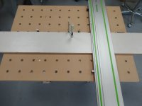
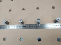
I then made a series of system holes on both longer sides using the 5mm router bit provided with the kit. These are not through holes, only about 15 mm deep.
I used the end stop accessory on the rail to ensure correct position of each adjacent row of holes.
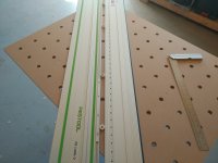
Router bit is a cheap 20 mm bottom cleaning bit from China.

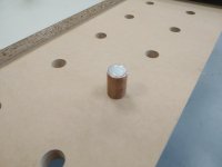
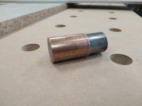
I think these images provide enough information to be clear what I have done.

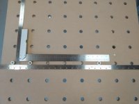
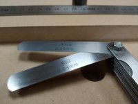
I am aware that there are possible errors in this method, but during the work I felt that it might be precise. I don't have bench dogs yet to check for squareness of rows and columns. I will update this post when I made the test.

Best regards
Adam from Hungary
 

Attachments

  • IMG_20200918_173850.jpg
    IMG_20200918_173850.jpg
    271.9 KB · Views: 940
  • IMG_20200918_192200.jpg
    IMG_20200918_192200.jpg
    169.7 KB · Views: 899
  • IMG_20200918_185059.jpg
    IMG_20200918_185059.jpg
    226 KB · Views: 859
  • IMG_20200918_184152.jpg
    IMG_20200918_184152.jpg
    258.5 KB · Views: 890
  • IMG_20200918_180124.jpg
    IMG_20200918_180124.jpg
    195.3 KB · Views: 761
  • IMG_20200918_174447.jpg
    IMG_20200918_174447.jpg
    236.4 KB · Views: 837
Very well done.  Let us know how perpendicular the holes came out to be,  What did you do to make sure that the row to row distance was maintained at 96 mm.
 
box185 said:
vkumar said:
Very well done.  Let us know how perpendicular the holes came out to be,  What did you do to make sure that the row to row distance was maintained at 96 mm.

Looking at the OP's steps, "I used the end stop accessory on the rail to ensure correct position of each adjacent row of holes."

It appears in the third image where you can see the end stop accessory butted up against the MDF on the right side of the guide rail.

Got it. Very well executed.
 
box185 said:
vkumar said:
Very well done.  Let us know how perpendicular the holes came out to be,  What did you do to make sure that the row to row distance was maintained at 96 mm.

Looking at the OP's steps, "I used the end stop accessory on the rail to ensure correct position of each adjacent row of holes."

It appears in the third image where you can see the end stop accessory butted up against the MDF on the right side of the guide rail.

EDIT: Or maybe it's on the left side as more clearly shown in the fifth image.

In fact, row-to-row distance is set by the two drill bits in every 3rd system holes to which the guide rail is butted up against.
Most of these holes are innecessary, but I had not done any planning beforehand and thought "more holes" is "more options to change my mind" before mounting the 20 mm router bit.

Column-to-column distance is of course provided by the LR32 rail.

The end stop is not for the 96 mm spacing. It is for consistent edge-to-column spacing. In other words it is to prevent skewing of the hole lines.
The third image was not intended to show the end stop, I changed my mind and put that under the left end of the rail before I started the boring process. (pun intended)

Speaking of (not) boring. I am surprised how fast this whole process went. Under one hour from unboxing the LR32 kit to the last 20 mm hole.
I am also surprised how clean and precise holes are made with that the cheap chinese 20 mm bottom cleaning router bit.
(I have already checked the hole diameters with a brass rod exactly 20 mm in diameter - nice friction fit.)

Achieved (or failed) squareness to be announced when I got some proper bench dogs.
 
[member=72127]elekes.adam[/member] , thanks for posting this. I have the LR-32 and have the same need. I may give your approach a try. I was going to ask why you drilled all of the 5mm holes but you answered that well in the last post. Please do let us know what you find regarding accuracy.
Thanks.
 
  Yes I dont need to use this method but Im curious as well how accurate it is, since I appreciate a little creative thinking to solve common problems/solutions.  I have never checked the accuracy of the LR32 hole spacing but as long as that is accurate and the guide holes are 100% square to start it looks like a viable solution. 
 
So today I found a plastic thingy with 20 mm outer diameter and cut four small cylinders out of it to make the initial "test dogs" for my MFT top. Then I thought why not make some proper bench dogs out of metal.

I went to the metal scrap section of the workshop and found a meter long 20 mm steel rod. It is around 19.99 - 20.01 mm so quite precise for an ordinary cold formed steel rod. It is not hardened or machined or anything.

They are a nice friction fit now. They will certainly get loose with the holes wearing out, then I can add a sleeve to them made from 22mm OD copper pipe. The copper sleeve is a strong friction fit on the steel cylinder, no glue required. Bench dogs as cheap as it can be. You can also see an oversized bench dog on one of the photos.

First I checked the holes' alignment with a couple of squares, rulers and guide rails. I went through different configurations (see pictures below) and could not see any light shining through between dogs and measuring devices.

This quick success bothered me to the level that I searched through my drawers to find my feeler gauge. You won't believe this. I could not find a configuration where I could easily slide in 0.06 mm. I deliberately made some situations to multiply the errors (two dogs close together and a third one as far away as possible), then I just barely could slide in 0.04 mm and some places 0.05 mm.

In other words, an average human cell would have a hard time to fit through those gaps. Crazy, huh?

I think I can now call this project a success. What do you think?


Attachments

  • IMG_20200921_151315.jpg
    IMG_20200921_151315.jpg
    562 KB · Views: 430
  • IMG_20200921_151135.jpg
    IMG_20200921_151135.jpg
    773.9 KB · Views: 453
  • IMG_20200921_151015.jpg
    IMG_20200921_151015.jpg
    584 KB · Views: 421
  • IMG_20200921_150721.jpg
    IMG_20200921_150721.jpg
    587.7 KB · Views: 428
  • IMG_20200921_150426.jpg
    IMG_20200921_150426.jpg
    362.2 KB · Views: 544
  • IMG_20200921_145351.jpg
    IMG_20200921_145351.jpg
    796.2 KB · Views: 450
  • IMG_20200921_145125.jpg
    IMG_20200921_145125.jpg
    611.8 KB · Views: 460
  • IMG_20200921_144513.jpg
    IMG_20200921_144513.jpg
    472.6 KB · Views: 544
Additional photos.
 

Attachments

  • IMG_20200921_183501.jpg
    IMG_20200921_183501.jpg
    631.9 KB · Views: 364
  • IMG_20200921_182558.jpg
    IMG_20200921_182558.jpg
    876.3 KB · Views: 426
  • IMG_20200921_180840.jpg
    IMG_20200921_180840.jpg
    465.8 KB · Views: 472
  • IMG_20200921_172056.jpg
    IMG_20200921_172056.jpg
    460.2 KB · Views: 341
  • IMG_20200921_172021.jpg
    IMG_20200921_172021.jpg
    418.2 KB · Views: 391
  • IMG_20200921_171053.jpg
    IMG_20200921_171053.jpg
    615.3 KB · Views: 414
  • IMG_20200921_171039.jpg
    IMG_20200921_171039.jpg
    626.3 KB · Views: 390
  • IMG_20200921_170203.jpg
    IMG_20200921_170203.jpg
    655 KB · Views: 427
  • IMG_20200921_183602.jpg
    IMG_20200921_183602.jpg
    663 KB · Views: 399
Yep looks good. I wouldnt get to concerned with trying to sleeve holes.  My tops typically get all cut up and worn out before I need to start worrying about the dogs being to loose. Since the system looks easy, fast and MDF is cheap its probably easier to just make a new one.  I have been happy with the parf dogs from axminster.  They fit well and are budget friendly.  The only negative is the tall dogs hit the saw motor when cutting 18mm stock unless you have enough room to clear the saw at the front and back of the cut.  I wish they had a shorter pair but you can easily cut a pair down.  The parf anchor dogs work good for making adjustable stops and jigs too. 
 
Yes, I did rotate the guide rail for the second set of 5 mm holes, simply because I had to. The router sled does not fit of the rail the other way around.
I trusted the hole spacing on the rail to be as consistent as it needs to be.
One thing to mention here. The spring loaded pin in the router sled has a tiny-tiny bit of slack in the holes of the track. When using the sled I made sure to always reference form the same position by pushing the router towards the same direction (preferably away from the end stop) after the pin engages and while making the holes.
 
[member=72127]elekes.adam[/member] ; very nice result.

The story about surface vs holes wearing out; the original MFT top is HDF, not MDF; that might have something to do with it.

I expected that one day I would make a MFT top too when I bought the MFT, but the top is lasting way, way, way longer than I expected.
 
The story about surface vs holes wearing out; the original MFT top is HDF, not MDF; that might have something to do with it.

Im assuming you are saying the factory MFT top is HDF not MDF... Since the OP said it was MDF.  I dont have a "festool" MFT mine is a 4x8 workbench with a MFT "style" top. So im not sure what the MFT has on from the factory.  HDF can be pretty hard to find by most.  I would hazard to guess those that make their own tops or replacement MFT tops almost all use MDF. Even the MDF holes seem to last a long time. I think thats because most operations on the MFT put very little stress laterally on the holes and since the dogs fit so precisely they do a good job of distributing any lateral load.  I dont think I have ever had an egg shaped hole issue. 

I have only made 4x8 sized tops and can say that the thing that makes me second guess just tossing a sheet up there and cutting all willy nilly is the thought of making another one not the cost.  The MDF is cheap enough it doesn't bother me but the time it takes to make one with the parf guide is a completely different story.  A smaller top or one with just a few rows of holes for a cutting station wouldnt be so bad.  However I like having holes everywhere for using stops or clamping holes. Spending hours drilling several hundred holes X 2 gets old quickly for me, especially since you have to be mindful of keeping everything square, straight and flip flopping that orange guide all around popping pins and dogs in and out etc.  I always liked the looks of the DominoFX style jig and it seemed like it would be much faster but no one would ever do a 4/5 cut test.  Peter was always very transparent with testing the Parf guide so he got my money.  I would have tried this LR32 method first though if I was doing it again since it would seem like it would be much faster and I already had the LR32. If I was still going to be making MFT style tops by hand than I would ask the OP or make one and do a 4/5 cut test myself.  That will be the true test of how well it works. I will also say for dead accurate cuts I have found it best to use an 80/20 rail that attaches/detataches in seconds using 2 angles and parf anchor dogs as a fence and use of a Festool style rail hinge. gives the most accurate cut and provides easy way to have multiple stops. So if the holes are off a slightly Im not as concerned since cut squareness is adjusted via the rail hinge now or shimming between the 80/20 and angle bracket. 
 
I don’t own the of1400, the rail guide, nor a long enough track to feel confident that everything is straight, square and perpendicular? +1 Peter Perfitt/ TSO got my funds. Either that or take it to my local woodshop that has a 5x10 foot CNC and have them do the job?  I wanted to design my own custom top. Their labor I think was $125/ hour. So I decided for the first bench, a cutting station I would go smaller and keep the fabrication in-house,instead of outsource.
 
[member=73094]afish[/member] ; original MFT top is HDF. I explicitly mention it because it will make the cost of an original replacement top seem a lot less sour. Try to source HDF... it's rare, hard to find and expensive as heck.

Making your own top with LR 32 jig out of MDF will never yield the same end product as it is MDF not HDF.

There are some threads on this forum on where to source HDF and it seems it's hard in general and nobody stocks it; special order all the way.
 
Coen said:
[member=73094]afish[/member] ; original MFT top is HDF. I explicitly mention it because it will make the cost of an original replacement top seem a lot less sour. Try to source HDF... it's rare, hard to find and expensive as heck.

Making your own top with LR 32 jig out of MDF will never yield the same end product as it is MDF not HDF.

There are some threads on this forum on where to source HDF and it seems it's hard in general and nobody stocks it; special order all the way.

Yes Im aware of the difficulty sourcing HDF I have had several tops made from MDF and my point was that the top gets damaged from cutting on it before the holes wear out (even when using MDF) .  This will depend on the user too as I know some like to use spacers or sacrificial piece so they are not cutting the actual MFT top.  If one has a quick way to make a new top then it becomes a mute point for me. Even a heavily used top mdf top will last a long time. I was getting about 6 months out of a top cutting on it without a care. I believe I can buy the HDF locally but never needed to yet.  MDF and a few coats of lenmar sealer if you want some extra durability.  I wouldnt spend the money for HDF just to cut on it but Im thrifty.
 
I use the side-ways clamps a lot, without using the part that goes under the top. That puts a lot of extra wear on the holes.
 
Back
Top