Festool Domino 500. Miter Box Joint and ½” stock.
Problem: Breakthrough of cutter to outside face of stock.
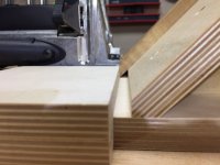
Anyone who has tried to use the Domino 500 to add 4 X 20 tenons to a miter box joint on ½” stock has found out the hard way that the cutter breaks through to the show face.
I have built a jig that not only eliminates this problem but also provides some significant side benefits.
View attachment 1
Instead of describing in detail the jigs I have built I will lay out the concept with a few key details. Hopefully you have an application for the concept and custom design your own jig.
So why bother with ½” stock. Well, in my case it’s because I make small jewelry and keepsake boxes with ½” stock. The boxes are between 3” and 5” high and between 4” and 10” wide. This presents another problem for me in that the box parts are small and hard to hold in position even if I could use the machine for ½” stock. I solved both problems by building a jig that eliminates the breakthrough problem and holds my box parts in a rock solid position for mortising. The end results are indestructible joints and no visible mechanical fasteners.
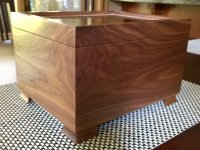
I have done over 60 boxes so far with my jigs and the results are always great. Be careful when dry fitting. Even without glue these joints are hard to get apart.
View attachment 2
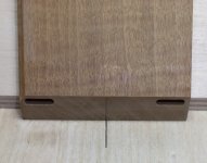
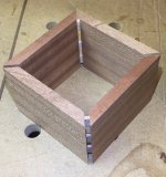
Here are but 2 examples that I put together with the Domino 500 Miter Box Joint Jig.
View attachment 3View attachment 4
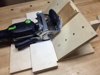
The basic jig consists of a 45 degree ramp and a base-plate for the machine.
View attachment 5
View attachment 6
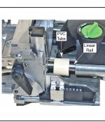
The ramp holds the workpiece in position so that the miter face is vertical. The base plate has a dual purpose. First, it holds the machine in a horizontal position for mortising into the vertical miter face. Second, it elevates the machine up to a level that prevents breakthrough. The cleats register the base-plate and machine on the ramp. I make my base-plates with 5/8” or ¾” Baltic birch. I make a shallow wide dado for the machine to sit in. This gives it lateral stability. I only remove enough material so I end up with the desired plate thickness below the dado. The machine is attached to the base-plate using countersunk M5 screws from the bottom of the base-plate.
The two key measurements required to determine the thickness of the base plate are the depth of cut of the mortise and the height of the cutter above the base of the machine. I got these by setting the machine on a flat surface and driving the 4 mil cutter into a piece of ¾” scrap plywood. The mortise is 10.5mm deep and the base of the cutter is 8.5mm above the surface. The top of the cutter is of course 12.5 mm above the surface.
A simple sketch showed me that the base of the cutter has to be more than 10.5mm above the surface to prevent blowing through to the show face, but less than 15mm above the surface to prevent cutting into the inside face of the box part. A 4.5 mm plate splits the difference nicely, providing good offset to both faces of the box part. I went with 3/16” which is pretty close to 4.5mm.
View attachment 7
I mill my parts to slightly proud of ½” so I end up with a miter face that is ¾” high, or 19mm.
View attachment 8
View attachment 9
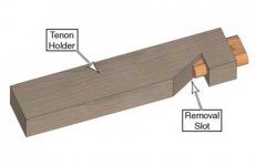
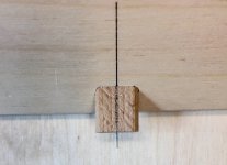
One critical aspect is to determine the exact center of the cutter and mortise relative to the ramp. This gives the jig outstanding accuracy. To do this simply put the machine with baseplate on the ramp. Snug up to the ramp and drive the cutter in. Mark a center line on a tenon, stick it into the mortise and transfer the center line from the tenon to the ramp.
View attachment 10
View attachment 11
The mortise will be perfectly centered on your line.
That is the basic concept. Hopefully you can come up with ways to use it.
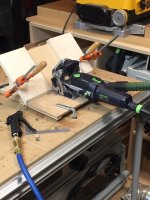
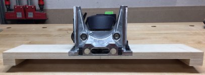
My favorite set up is shown below. I added side stops to the ramp. They are especially useful when I do large batches of boxes. Once I have my machine in the position that I want relative to the ramp, I lock it down with clamps on the MFT. I measure off the distance I need between the center line on the ramp and the edge of the side stops for the desired mortise location. The side stops are then clamped to the ramp in position for repetitive mortising. Slide the box parts down next to the side stop and away you go. The box part is up against the side stop and the miter face is registered against the front edge of the base plate. No pencil marks required. Even my smallest parts are easily held in position with one hand while the other hand operates the machine.
View attachment 12View attachment 13
Problem: Breakthrough of cutter to outside face of stock.
Anyone who has tried to use the Domino 500 to add 4 X 20 tenons to a miter box joint on ½” stock has found out the hard way that the cutter breaks through to the show face.
I have built a jig that not only eliminates this problem but also provides some significant side benefits.
View attachment 1
Instead of describing in detail the jigs I have built I will lay out the concept with a few key details. Hopefully you have an application for the concept and custom design your own jig.
So why bother with ½” stock. Well, in my case it’s because I make small jewelry and keepsake boxes with ½” stock. The boxes are between 3” and 5” high and between 4” and 10” wide. This presents another problem for me in that the box parts are small and hard to hold in position even if I could use the machine for ½” stock. I solved both problems by building a jig that eliminates the breakthrough problem and holds my box parts in a rock solid position for mortising. The end results are indestructible joints and no visible mechanical fasteners.
I have done over 60 boxes so far with my jigs and the results are always great. Be careful when dry fitting. Even without glue these joints are hard to get apart.
View attachment 2
Here are but 2 examples that I put together with the Domino 500 Miter Box Joint Jig.
View attachment 3View attachment 4
The basic jig consists of a 45 degree ramp and a base-plate for the machine.
View attachment 5
View attachment 6
The ramp holds the workpiece in position so that the miter face is vertical. The base plate has a dual purpose. First, it holds the machine in a horizontal position for mortising into the vertical miter face. Second, it elevates the machine up to a level that prevents breakthrough. The cleats register the base-plate and machine on the ramp. I make my base-plates with 5/8” or ¾” Baltic birch. I make a shallow wide dado for the machine to sit in. This gives it lateral stability. I only remove enough material so I end up with the desired plate thickness below the dado. The machine is attached to the base-plate using countersunk M5 screws from the bottom of the base-plate.
The two key measurements required to determine the thickness of the base plate are the depth of cut of the mortise and the height of the cutter above the base of the machine. I got these by setting the machine on a flat surface and driving the 4 mil cutter into a piece of ¾” scrap plywood. The mortise is 10.5mm deep and the base of the cutter is 8.5mm above the surface. The top of the cutter is of course 12.5 mm above the surface.
A simple sketch showed me that the base of the cutter has to be more than 10.5mm above the surface to prevent blowing through to the show face, but less than 15mm above the surface to prevent cutting into the inside face of the box part. A 4.5 mm plate splits the difference nicely, providing good offset to both faces of the box part. I went with 3/16” which is pretty close to 4.5mm.
View attachment 7
I mill my parts to slightly proud of ½” so I end up with a miter face that is ¾” high, or 19mm.
View attachment 8
View attachment 9
One critical aspect is to determine the exact center of the cutter and mortise relative to the ramp. This gives the jig outstanding accuracy. To do this simply put the machine with baseplate on the ramp. Snug up to the ramp and drive the cutter in. Mark a center line on a tenon, stick it into the mortise and transfer the center line from the tenon to the ramp.
View attachment 10
View attachment 11
The mortise will be perfectly centered on your line.
That is the basic concept. Hopefully you can come up with ways to use it.
My favorite set up is shown below. I added side stops to the ramp. They are especially useful when I do large batches of boxes. Once I have my machine in the position that I want relative to the ramp, I lock it down with clamps on the MFT. I measure off the distance I need between the center line on the ramp and the edge of the side stops for the desired mortise location. The side stops are then clamped to the ramp in position for repetitive mortising. Slide the box parts down next to the side stop and away you go. The box part is up against the side stop and the miter face is registered against the front edge of the base plate. No pencil marks required. Even my smallest parts are easily held in position with one hand while the other hand operates the machine.
View attachment 12View attachment 13
Attachments
-
 box miter jig.jpg133 KB · Views: 1,068
 -
 box miter jig.jpg133 KB · Views: 837
 -
 center.jpg294.9 KB · Views: 766
 -
 center line.jpg545.4 KB · Views: 732
 -
 IMG_3012.JPG1.7 MB · Views: 1,221
 -
 IMG_3016.JPG673 KB · Views: 1,844
 -
 01-sketch.jpg656.4 KB · Views: 803
 -
 base-plate.jpg447.1 KB · Views: 753
 -
 Ramp.jpg551.2 KB · Views: 831
 -
 sarah box.jpg737.3 KB · Views: 745
 -
 image 2.JPG372.5 KB · Views: 882
 -
 box mitre joint.jpg275.4 KB · Views: 2,784