smorgasbord
Member
- Joined
- Jan 7, 2022
- Messages
- 1,058
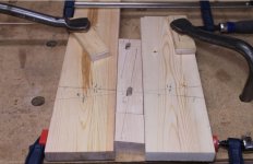
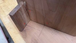
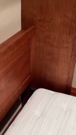
I built this jig to help me locate domino mortises in the face of a big plywood panel. This was for my Murphy Bed, which has a headboard that is located kind of arbitrarily in the side panel (sometimes at an angle) and for me was a U-shaped assembly (Headboard itself plus a top shelf and bottom piece) with mortises in the end grain of the headboard pieces, so locating precisely in the side panel was important.
[attachimg=1]
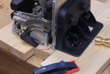
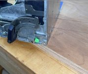
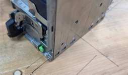
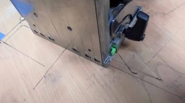
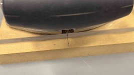
The top shelf of the headboard was narrower than the Domino machines, so I didn't have marks on the side closest to the back vertical edge, making alignment difficult. Here's an example:
[attachimg=4]
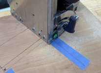
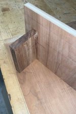
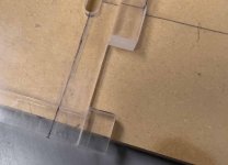
And even sighting from the side is tough, with parallax error opportunities:
[attachimg=5]
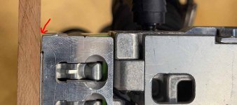
In addition, the markings on the side of the Domino showing distance of centerline from the base (10mm for DF500, 15mm for my DF700) are pretty thick and I found not completely accurate (for me the bottom of the wide mark was the centerline, not the center of the mark).
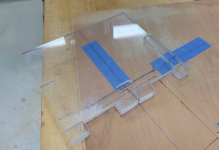
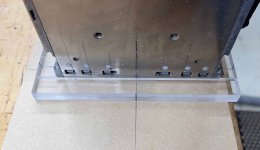
Here's the jig I came up with:
[attachimg=2]
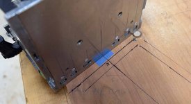
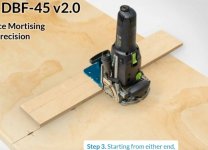
It's basically a piece of 5mm thick polycarbonate with centerline markings everywhere (top, bottom, sides) and some additional pieces glued onto it to hold the Domino itself in place. Here are some shots of the jig located:
[attachimg=3]
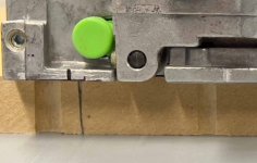
The jig was great for those mortises close to the edge:
[attachimg=6]
(Yes, that's after the mortise was cut)
Even at the top end there's an alignment line on the jig:
[attachimg=7]
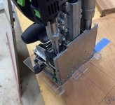
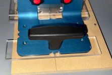
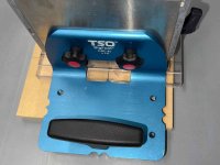
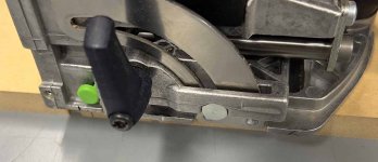
And I made the jig to accommodate the TSO Big Foot:
[attachimg=8]
[attachimg=9]
The Big Foot needs a spacer to be at the same 5mm off as the jig, but that's not a problem, there are even tapped holes in the big foot:
[attachimg=10]
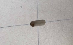
And finally, the mortise:
[attachimg=11]
If I had made the jig bigger, I could have clamped it to the side panel all aligned and then simply place the Domino machine into it and cut. You do have to remember to cut 5mm deeper than you want due to the thickness of the jig's base, but that's easy. And even on the DF500, cutting a face mortise 23mm deep is often more than plenty (will go through ¾" plywood and then some).
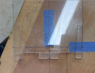
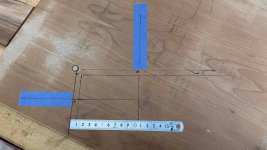
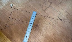
For my Murphy Bed, I cut the mortises in the ends of the assembled headboard unit first, leaving the alignment center lines alone (they're behind the headboard so not visible in the final product. I then laid the side panel face up, located the headboard standing on its edges and drew in the centerline and the base line, which is the edge of the headboard panels where they meet the side. I drew those on blue tape. Then I measured 9mm in from the base line (which was the fence setting I used to cut the edge mortises) to get the centerline of the needed mortise. This 9mm offset line and the usual domino center lines were extended and are what I used to align the jig against.
Now, this would have been a bit simpler with a DF500, in that I could have used the standard 10mm offset for both the edge mortises in the headboard itself (with a Seneca 0" Offset plate or similar) and then go to align the base of the Domino for the face mortises, but I'd still have the problem of the Domino base hanging off the edge with no good way to align it there.
And with this clear jig, you get to see where the mortise is going to go, so if you took a second to draw it in, you'd have confidence that's where it's going. This was important to me because I messed one up, luckily during a test pass.
Anyway, I'm happy with this jig and expect to use it again some day. Some friends of mine were over and after admiring my Murphy Bed we went in the shop and talked about building it. One of them thought this jig is something I should make (using a CNC instead of hand building) and perhaps offer as a product for other woodworkers. I'm not sure my face mortising challenges are something others have run into, but here I am, asking. You could, of course, build this for yourself as I did, but sometimes it's easier and more accurate to buy an accurately machined jig.
Thoughts?
[attachimg=1]
The top shelf of the headboard was narrower than the Domino machines, so I didn't have marks on the side closest to the back vertical edge, making alignment difficult. Here's an example:
[attachimg=4]
And even sighting from the side is tough, with parallax error opportunities:
[attachimg=5]
In addition, the markings on the side of the Domino showing distance of centerline from the base (10mm for DF500, 15mm for my DF700) are pretty thick and I found not completely accurate (for me the bottom of the wide mark was the centerline, not the center of the mark).
Here's the jig I came up with:
[attachimg=2]
It's basically a piece of 5mm thick polycarbonate with centerline markings everywhere (top, bottom, sides) and some additional pieces glued onto it to hold the Domino itself in place. Here are some shots of the jig located:
[attachimg=3]
The jig was great for those mortises close to the edge:
[attachimg=6]
(Yes, that's after the mortise was cut)
Even at the top end there's an alignment line on the jig:
[attachimg=7]
And I made the jig to accommodate the TSO Big Foot:
[attachimg=8]
[attachimg=9]
The Big Foot needs a spacer to be at the same 5mm off as the jig, but that's not a problem, there are even tapped holes in the big foot:
[attachimg=10]
And finally, the mortise:
[attachimg=11]
If I had made the jig bigger, I could have clamped it to the side panel all aligned and then simply place the Domino machine into it and cut. You do have to remember to cut 5mm deeper than you want due to the thickness of the jig's base, but that's easy. And even on the DF500, cutting a face mortise 23mm deep is often more than plenty (will go through ¾" plywood and then some).
For my Murphy Bed, I cut the mortises in the ends of the assembled headboard unit first, leaving the alignment center lines alone (they're behind the headboard so not visible in the final product. I then laid the side panel face up, located the headboard standing on its edges and drew in the centerline and the base line, which is the edge of the headboard panels where they meet the side. I drew those on blue tape. Then I measured 9mm in from the base line (which was the fence setting I used to cut the edge mortises) to get the centerline of the needed mortise. This 9mm offset line and the usual domino center lines were extended and are what I used to align the jig against.
Now, this would have been a bit simpler with a DF500, in that I could have used the standard 10mm offset for both the edge mortises in the headboard itself (with a Seneca 0" Offset plate or similar) and then go to align the base of the Domino for the face mortises, but I'd still have the problem of the Domino base hanging off the edge with no good way to align it there.
And with this clear jig, you get to see where the mortise is going to go, so if you took a second to draw it in, you'd have confidence that's where it's going. This was important to me because I messed one up, luckily during a test pass.
Anyway, I'm happy with this jig and expect to use it again some day. Some friends of mine were over and after admiring my Murphy Bed we went in the shop and talked about building it. One of them thought this jig is something I should make (using a CNC instead of hand building) and perhaps offer as a product for other woodworkers. I'm not sure my face mortising challenges are something others have run into, but here I am, asking. You could, of course, build this for yourself as I did, but sometimes it's easier and more accurate to buy an accurately machined jig.
Thoughts?
Attachments
-
 Headboard.jpg47.9 KB · Views: 898
 -
 TheMortise.jpg47.3 KB · Views: 830
 -
 BigFootNeedsSpacer.jpg72 KB · Views: 827
 -
 WithBigFoot.jpg34.4 KB · Views: 831
 -
 AccommodatesBigFoot.jpg57.3 KB · Views: 828
 -
 FarEndAlignment.jpg39.1 KB · Views: 829
 -
 JigAfterMortiseInPlace.jpg46.8 KB · Views: 826
 -
 OVerEdgeParallax.jpg41.4 KB · Views: 882
 -
 TooCloseToEdge.jpg41.1 KB · Views: 891
 -
 FaceJig2.jpg49.6 KB · Views: 825
 -
 TheJig.jpg47.9 KB · Views: 830