derekcohen
Member
- Joined
- Jun 22, 2008
- Messages
- 1,060
Between furniture builds I either build a tool, such as a hand plane or cutting gauge or something, or tune up equipment. In the current situation, I tuned up a fixture I built. This was posted at an earlier time, but I have made a few changes, and now it is perfect! ") I offer the ideas for others who wish to make their own.
I offer the ideas for others who wish to make their own.
The model for the double mitre gauge is the Felder EGL 1350 ...
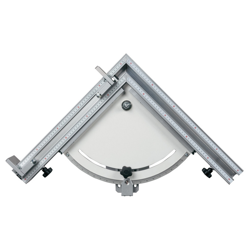
Or, as Felder term it, "Electronic Double-Cut Mitre Gauge". Is that over-kill, or is that over-kill!
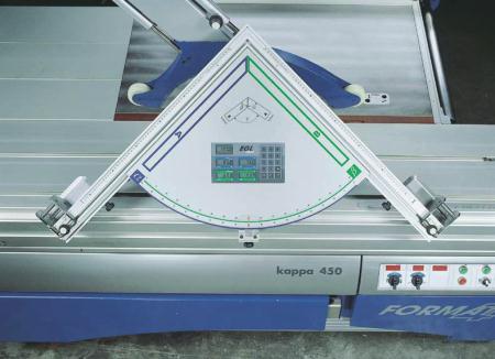
That is some serious double mitre gauge!
Well, mine is not electric, but it is accurate.
One of my early inspirations to build my own manual version was this shop made version ...
http://www.youtube.com/watch?time_continue=8&v=BG9LRnB9-Hg&feature=emb_logo
The one I built is significantly easier to set up. However, I do like how this version works. He did a good job.
The key element in a gauge such as this is that the corner is a perfect 90 degrees. Not a smidgeon less or a smidgeon more. The aim is to make the two sides of the apex complimentary, that is, they will add up to exactly 90 degrees. When this is the case, it does not matter if one side is set to 44 degrees as long as the other measures 46 degrees. When added together, the corners end up a square 90 degrees.
The corner must not only be 90 degrees, but the sides of the gauge must also be 90 degrees to the table (of the slider), otherwise one produces compound angles. That would not end up well.
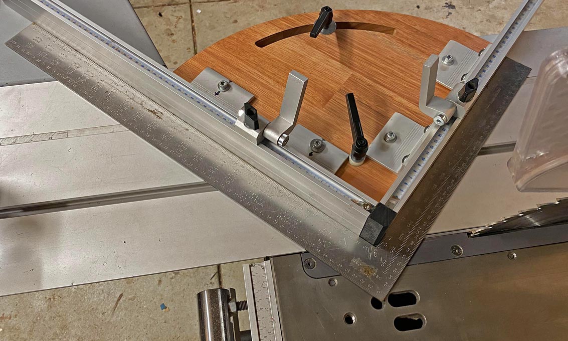
This is my version for the Hammer K3 ...
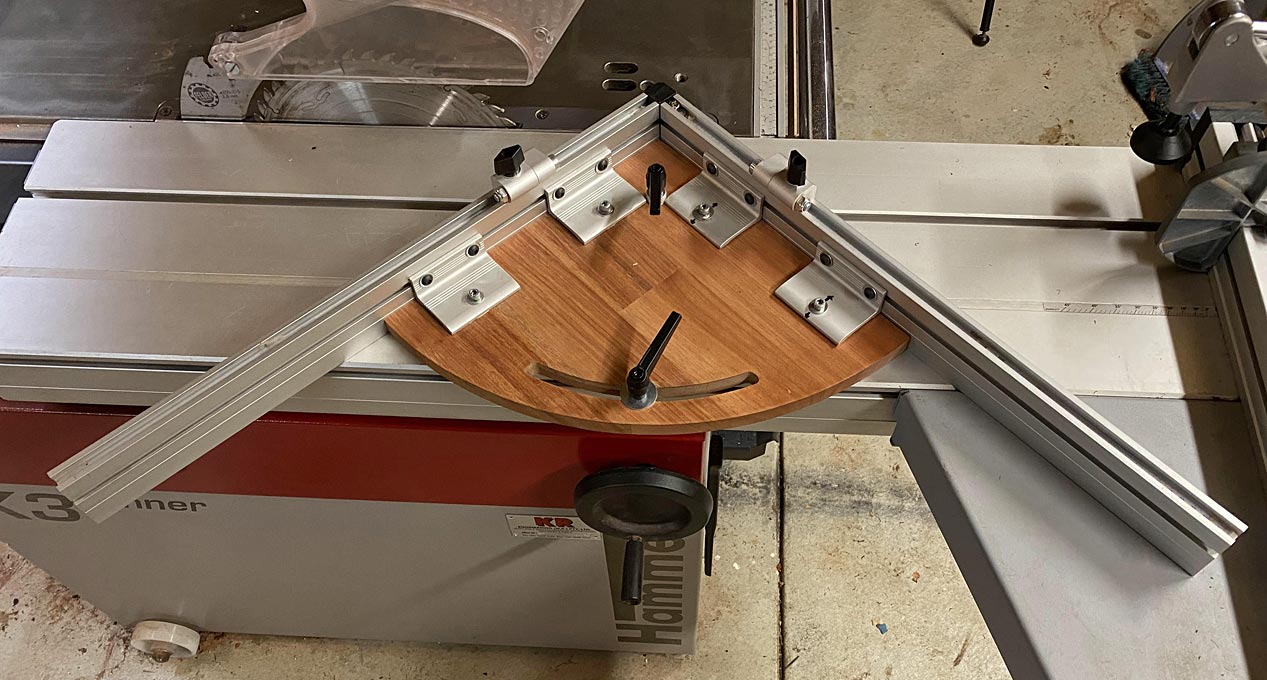
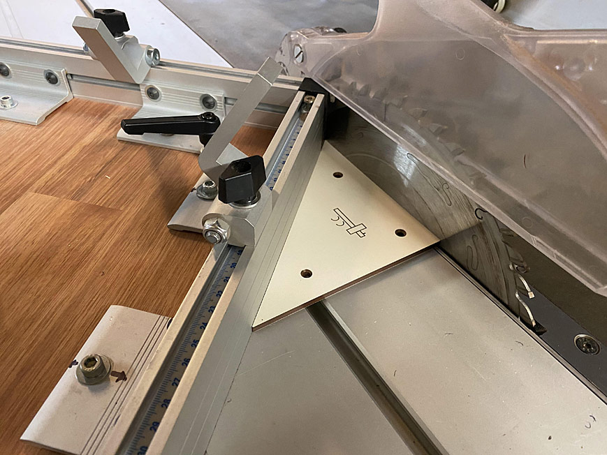
Here is a close up for the parts ...
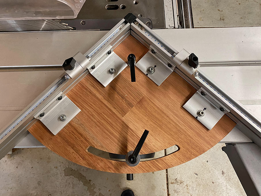
The obvious parts include the side fences with sliding stops (these were purchased as accessories for a router table, drill press table, or similar). As we know, the stops are important to repeat measurement. These stops can be set to 0.05mm.
The left fence is attached in a permanent position. The right fence is adjustable. The internal braces can move back-and-forth (on lengthened bolt holes) to adjust the angle at the corner (if you cannot build it exact, made it adjustable). The right fence can also slide to position the black UHMW block. This block is attached to the right side, perfectly flush with it, and is then moved to be perfectly in line with the left side.
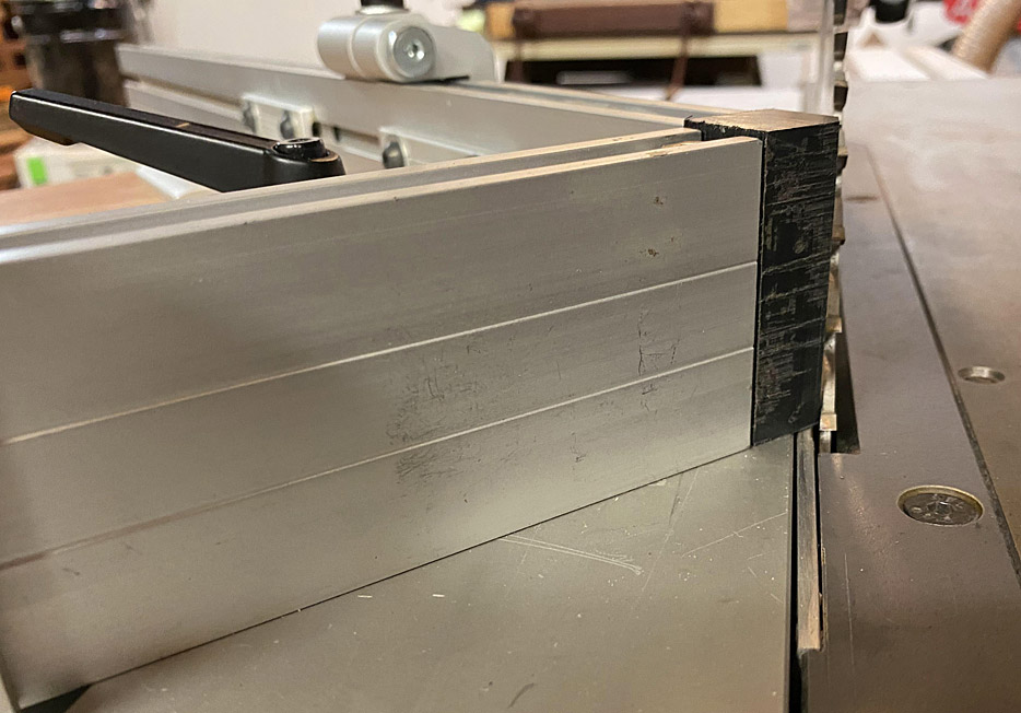
The block becomes a zero clearance mark for each cut.
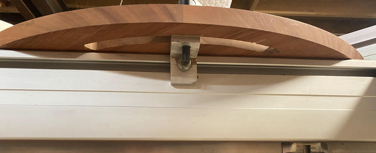
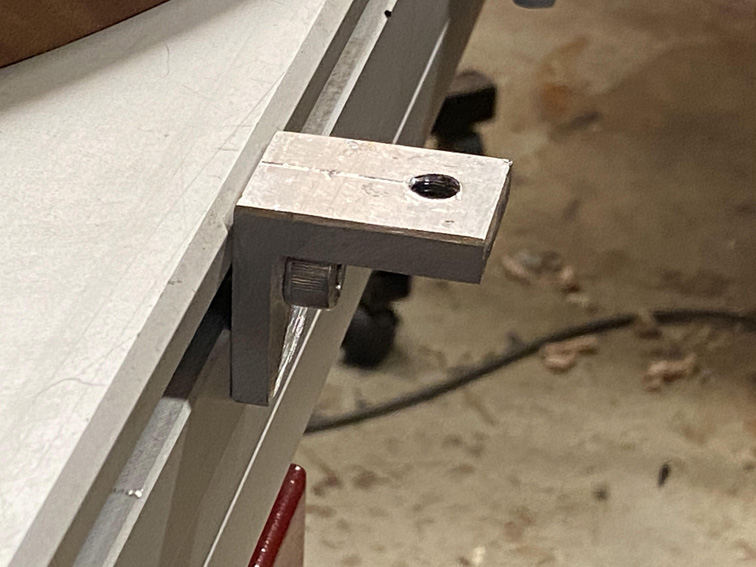
The other controls include the forward lever, which secures a pivot in the slider slot. The rear lever secures the outside of the gauge. Together, these set the adjustment for the angle of the mitre.
This gauge is centred on 90 degree mitres, and setting it up demonstrates how to achieve the precision needed.
First both sides are set up to be perfectly square to the table ...

Then the left side is set to a perfect 45 degrees to the saw blade ...
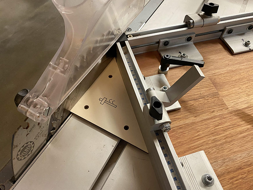
Followed by the right side ...
Tighten it all down. And then you go through it all again to ensure nothing has moved.
It should be square ...
Regards from Perth
Derek
I offer the ideas for others who wish to make their own.The model for the double mitre gauge is the Felder EGL 1350 ...
Or, as Felder term it, "Electronic Double-Cut Mitre Gauge". Is that over-kill, or is that over-kill!
That is some serious double mitre gauge!
Well, mine is not electric, but it is accurate.
One of my early inspirations to build my own manual version was this shop made version ...
http://www.youtube.com/watch?time_continue=8&v=BG9LRnB9-Hg&feature=emb_logo
The one I built is significantly easier to set up. However, I do like how this version works. He did a good job.
The key element in a gauge such as this is that the corner is a perfect 90 degrees. Not a smidgeon less or a smidgeon more. The aim is to make the two sides of the apex complimentary, that is, they will add up to exactly 90 degrees. When this is the case, it does not matter if one side is set to 44 degrees as long as the other measures 46 degrees. When added together, the corners end up a square 90 degrees.
The corner must not only be 90 degrees, but the sides of the gauge must also be 90 degrees to the table (of the slider), otherwise one produces compound angles. That would not end up well.
This is my version for the Hammer K3 ...
Here is a close up for the parts ...
The obvious parts include the side fences with sliding stops (these were purchased as accessories for a router table, drill press table, or similar). As we know, the stops are important to repeat measurement. These stops can be set to 0.05mm.
The left fence is attached in a permanent position. The right fence is adjustable. The internal braces can move back-and-forth (on lengthened bolt holes) to adjust the angle at the corner (if you cannot build it exact, made it adjustable). The right fence can also slide to position the black UHMW block. This block is attached to the right side, perfectly flush with it, and is then moved to be perfectly in line with the left side.
The block becomes a zero clearance mark for each cut.
The other controls include the forward lever, which secures a pivot in the slider slot. The rear lever secures the outside of the gauge. Together, these set the adjustment for the angle of the mitre.
This gauge is centred on 90 degree mitres, and setting it up demonstrates how to achieve the precision needed.
First both sides are set up to be perfectly square to the table ...
Then the left side is set to a perfect 45 degrees to the saw blade ...
Followed by the right side ...
Tighten it all down. And then you go through it all again to ensure nothing has moved.
It should be square ...
Regards from Perth
Derek