Electrical Short Issues

It also appears that you have a 40 amp 240 breaker that feeds with 12 gauge wire if you actually need 40 amps that requires 8 gauge. If you don’t need 40 amps then change the breaker. It looks like a 20 amp outlet. 10 gauge wire might be better choice
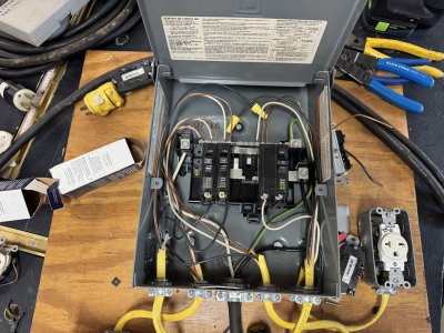
That's exactly what I was referring to in my earlier post. It appeared to me that those wires I pointed out were 14 AWG & 12 AWG. However, by looking at and comparing their diameters relative to each other, they now appear to be 12 AWG & 10 AWG but 10 AWG wire is only NEC ampacity rated at 30 Amps and a 40 Amp breaker requires 8 AWG wire. As Tom & Ron noted, a 50 Amp circuit requires 6 AWG wire.
 
It's definitely this. If the entire circuit were undersized, but the plug in good shape, you'd have all the thermal effects spread across the entire length of the circuit (and thus much lower intensity). That's not what this is.

Those "plug it yourself" thingies are always suss. Don't count on them lasting forever. Especially if no ferrules are used- and I'm the only person I've met in real life who uses them. Maybe you did, maybe you didn't.

Open neutrals- Tom's right about the danger, but the danger is in the unpredictability. It just means you'll have hot voltage where you're not expecting it. It won't cause the damage to be greater when a fault occurs. That's also not what's wrong here. This is a current path that was established, but then a physical connection problem that degraded the conductive path caused a runaway "thermal event" (which is a nice way to phrase it in front of customers....)
The danger is two fold, one voltage should not be there, you become the path if grounded. Second issue on a split phase system (commonly called single phase, the last time I saw a poly phase was in Philadelphia in the late 1990’s they had a few areas that hadn’t been updated yet) if there is any load on the circuit the voltage can be as high as the systems total voltage. On a 227V system the potential becomes 480V.

The cable shown is a neutral that the insulation was damage on when the utility company installed the service cables. About 8 years later it degraded to a point it came open. The system stayed in balance until a light was turned on. Total insurance cost to replace all of the appliances that got damaged and other issues was over 35K. The last two pictures are of various power conditioners he had on his stereo, they did their job protecting his stereo system that had a separate insurance rider of 100K. The insurance company cover the cost of new conditioners and having the components tested.

Simply put, do not take an open neutral lightly.

Tom
 

Attachments

  • IMG_0842.jpeg
    IMG_0842.jpeg
    941.2 KB · Views: 32
  • IMG_0838.jpeg
    IMG_0838.jpeg
    815 KB · Views: 18
  • IMG_0869.jpeg
    IMG_0869.jpeg
    937 KB · Views: 19
  • IMG_0860.jpeg
    IMG_0860.jpeg
    827.2 KB · Views: 19
What's up with this white wire (red arrow)?
Wire.jpg
They taped over the label on the circuit breaker. It kinda looks to my non-professional eye that this is a 240 volt circuit. But, in that case the white wire should be wrapped with black tape here (and at the other end) to indicate that it's no longer a neutral wire. Better would have been a red wire, if I'm right on this.
 
@onocoffee i’m with Tom on the feeder size. Double check that the feeder is 6 gauge and that the outlet you are plugging the feeder into is connected to the main with 6 gauge.

It also appears that you have a 40 amp 240 breaker that feeds with 12 gauge wire if you actually need 40 amps that requires 8 gauge. If you don’t need 40 amps then change the breaker. It looks like a 20 amp outlet. 10 gauge wire might be better choice

Ron
I will double-check on that main wire gauge today. But the 240v breaker is now 20A - and I'm pretty sure because I bought it myself (though it did cost $40).
 
What's up with this white wire (red arrow)?
View attachment 378055
They taped over the label on the circuit breaker. It kinda looks to my non-professional eye that this is a 240 volt circuit. But, in that case the white wire should be wrapped with black tape here (and at the other end) to indicate that it's no longer a neutral wire. Better would have been a red wire, if I'm right on this.
Black tape on white wire - good point. Seems that I forgot about that. Will do that later today. And to your point about the 40A, it was changed to a 20A yesterday.
 

Attachments

  • IMG_5423.jpeg
    IMG_5423.jpeg
    5 MB · Views: 30
What's up with this white wire (red arrow)?
View attachment 378055
They taped over the label on the circuit breaker. It kinda looks to my non-professional eye that this is a 240 volt circuit. But, in that case the white wire should be wrapped with black tape here (and at the other end) to indicate that it's no longer a neutral wire. Better would have been a red wire, if I'm right on this.
Per the NEC that NM should be a 12/3. The NEC allows tape ID for conductors 4ga or larger. That said, most AHJ’s have amended the code to allow tape ID on smaller wires. Yes that should have red tape on it at both ends as long as your AHJ has amended the adopted code.

As others have mentioned the 12ga is to small for a 40 amp breaker, you need 8ga for it.

Two other things.;

It looks like they used the black and white from the service/feeder cable to energize both busses. Then they are using the ground cable to act as a neutral, this is a really bad thing to do. That feeder cable needs to be a 6/3 cable.

This being a sub panel the grounds and neutrals cannot be tied/bonded together. There needs to be a separate ground bus.

I’m so glad I come from the land of EMT, we don’t need to be concerned with color coding wire, larger cables we do color code.

Tom
 
The stab-ins are 14ga, 15 amp circuit only.

In Chicago and most of the collar municipalities we cannot use any type of push in pressure connector.

Tom
 
The stab-ins are 14ga, 15 amp circuit only.

In Chicago and most of the collar municipalities we cannot use any type of push in pressure connector.

Tom
I'm a little surprised the insurance companies haven't rallied against stab-ins to have the codes revised to remove them?
 
Late to this thread, but somewhere back there, I read that you were using the same extension cord. Maybe check that. I had a 12ga extension reel on the ceiling of the shop and one day it quit working. Somehow, a neutral broke inside the cord when testing conductivity. If you were moving a cord around, I could see it making and breaking conductivity. So try a conductivity test on each wire of the extension (including ground) and move it around a bit to see if there's something broken. How it happened to my reel is beyond me.
 
I'm a little surprised the insurance companies haven't rallied against stab-ins to have the codes revised to remove them?
The insert/pressure connections are NEC approved for 15 amp circuits and must have a “listing” to be used on an inspected job in the US. By having a listing it indicates the device was tested to a pretty rigorous standard.

I have used the back stab method in some temporary situations I had to use quickly. I’ve never used a back stab on an “in service” application. WAGO connectors were not approved in Chicago up to 6 years ago that I know of (when I moved). We had to cut the factory WAGO’s out of can lighted and use wire nuts.

I used the word “listing” not UL. Any nationally recognized testing/listing agency is accepted.

Festool had to move away from the CE marking (in the US) because it is not a recognized listing agency in the US. They now use MET which is a US recognized listing agency.

Tom
 
Back
Top