Festool Drill Stand

The guide arrived today and just in time as we're getting battered with the first named storm of the year "Atiyah" which has cancelled all freight ferries for the next 2 days. Yay!

Packaging was top notch. Included were two spanners presumably for working with the chuck fixings. They were duly cast aside. There's a parts diagram and a fluffy manual of sorts with lots of photos. They joined the spanners.

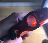
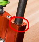
After wiping it down to remove protective oil the only thing left to do was attach the handle and tightening knob. The fit and finish is pretty good. Very little slop in the bushings riding the guide rods which is reassuring. If they were any tighter it wouldn't move so the tolerances look great in that respect.

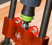
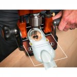
Chuck looks good but I fitted a Wera Rapidaptor as all my bits are 1/4" hex or Centrotec affairs and I don't fancy futzing around with a chuck key unless absolute accuracy is required.

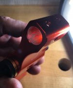
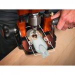
I thought the centring pins were missing but they helpfully screw in to two holes in the guide. Very handy and a nice touch to stop them from joining the pencil and tape measure MIA list.

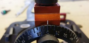
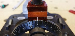
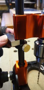
Adjusting the angle of attack is easy enough. Perhaps slightly on the just too tight but that can be adjusted. There are no positive stops for any common angles. Not even 0/90. To set that a good square wants using which is easy enough referencing of the base and the squared castings at the bottom of the rods. Locking in an angle is achieved simply by tightening the two handles. It feels solid but I'll need to give it some use to be able to trust it completely.

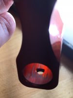
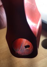
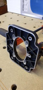
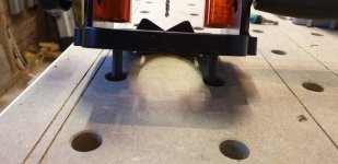
The only major gripe so far is the anti-slip sole which is a sheet of rubber glued on to ribs on the base. It's not a good fit and knocks the sole out of true meaning the whole unit rocks a bit. That's "not good". With a bit of gentle persuasion it came off and joined the manual in dust gather duties. The base itself has been ground / milled flat. I'll likely fashion a new base or set to easing the metal edges to prevent marking things.

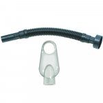
Another niggle will certainly be the lack of return springs to stop a fitted bit and drill from sliding down to the depth stops when set aside on the base. Such a mechanism would likely get in the way and clog up with dust so not a biggy really.

I'll not get a chance to actually use the thing until Thursday but first impressions are good. Thankfully!
 
[member=53696]Roachmill[/member] - I suppose if the guide rods can be slid out/base removed it would be a simple matter to find or make a compression spring and maybe fashion a couple of washers too to enable spring return. Might only need a spring on one guide rod (not both). Nice at least to have the option.

Thanks for your preliminary review! Now, if you make a video and upload it to youtube you'd be the first one to do so! ;) 
 
TinyShop said:
[member=61691]TSO_Products[/member] - I think you may have misunderstood. Please reread the quote of mine that you posted. I was asking specifically about the self-centering vise that is designed to fit the drill guide/stand. Obviously, you're going to stock the drill guide/stand (I've been signed up on that list forever). I just want to know about the vise. :)

[member=64030]TinyShop[/member] - thanks for clarifying - yes, of course we will have the Vise accessory in stock as well.
Your interest in this additional accessory is noted.

Hans
 
TinyShop said:
The UJK-version utilizes "Oilite bronze bushes" (or "bushings" for those of us on the other side of the Atlantic) while, at least from what is evident in the images and description, the no-frills version does not:

I had access to and reviewed an early version of the original UJK drill guide. The largest issue I found was the wear within the upper yoke assembly. It was constructed from aluminum and it scored easily. This prevented it from plunging smoothly and sometimes prevented it from plunging at all because of the stiction.

The photos presented are the LH side of the yoke, showing the top & bottom sides of the bore & the RH side of the yoke, showing the top & bottom sides of the bore. There was significant scoring on the upper & lower yoke bores caused by a misalignment between the rods that are attached to the base and the traveling yoke itself. 

[attachimg=1]

[attachimg=2]

[attachimg=3]

[attachimg=4]

If the new UJK drill guide has oilite bushings, I'd consider that to be a major improvement over the original version along with correcting the misalignment between the rods and the yoke.

[attachimg=5]
 

Attachments

  • UJK 4556-1 yoke top LH.jpg
    UJK 4556-1 yoke top LH.jpg
    317 KB · Views: 1,914
  • UJK 4557-1 yoke top RH.jpg
    UJK 4557-1 yoke top RH.jpg
    280 KB · Views: 1,916
  • UJK 4558-1 yoke bottom RH.jpg
    UJK 4558-1 yoke bottom RH.jpg
    222.7 KB · Views: 1,903
  • UJK 4559-1 yoke bottom LH.jpg
    UJK 4559-1 yoke bottom LH.jpg
    320.4 KB · Views: 1,941
  • New Version.jpg
    New Version.jpg
    16.6 KB · Views: 1,862
I just happened to notice that the page on Axminster's site dedicated to the UJK Drill Guide 2.0 has been updated, and now reflects the dreaded "Out of Stock" status. I wonder...are they really out-of-stock or is the team at Axminster regrouping after receiving here and here a couple of less than glowing reviews?

Whatever is up, I have to say that I'm pretty disappointed given that if something as obvious as a poorly executed "rubberised high friction pad" or misaligned scales managed to slip past the normally discerning eyes at the UJK tool division, I have to wonder what other problems may likewise have been overlooked.

Now, I certainly understand that it's not at all an easy thing to bring a tool like this to market. But, if this kind of poor design and quality control shows up in the first couple of reviews (particularly of a Version 2.0 - this isn't a "Model A" we're talking about) it doesn't bode well for those of us who have been waiting patiently for many moons for the updated version.

It's really too bad that the economics apparently didn't allow UJK to take the design and manufacture of a drill guide in-house as my guess is they would have really knocked one out of the park relative to what we've apparently ended up with: (yet) another Tawianese-version that lacks dust collection, features dual-scales which apparently aren't aligned with each other, is hampered by a base which, apparently - thanks to the inclusion of a poorly executed non-slip pad - is all wobbly and which, as a result of these deficiencies, may suffer from similar accuracy limitations to that which plague a $23 Woolfcraft competitor (the latter of which, as I've already pointed out elsewhere in this thread, can at least boast dust-collection).

Crossing my fingers that these most recent problems can be overcome before the container full of guides bound for N.A. gets loaded aboard its respective freighter.
 
[member=64030]TinyShop[/member] I wonder if they've actually sold out or just yanked it again...

I didn't get to it on Thursday but managed to squeeze in some shop time today with it. I'd removed the rubber base and checked the metal sole for flatness. It was rocking ever so slightly but that was due to an errant piece of rubber I'd missed. After I'd nipped that out it was solid. The metal edges weren't noticeably sharp but I took a bit of sandpaper to them just the same. Here you can see the ribs the rubber was glued to... terrible idea as it's only about 1mm thick. Something akin to a router base would be what I'd want to see for this price.
View attachment 3

I set the thing to 90 degrees using a Woodpecker mini square referencing of the top side. Using an 8mm Fisch brad point bit I drilled a series of holes through some random pine. I stopped the drill leaving the bit in the hole and checked to see if said bit was protruding square to the wood. As far as I could see it was. No pics of any of this I'm sorry to say but it's a tick in the right box as far as I'm concerned.
The Axminster review mentioned that the scales were offset on their unit. Mine are as pretty much bang on:
View attachment 4View attachment 5

The centring pins worked well. I didn't measure the exact centres but they're spacing  handily allows them to fit in two dog holes:
View attachment 2

One last thing that I really liked were the depth stops on the rods. They easily let you set a depth of cut much like you'd do with a router e.g. drop the bit to rest on the surface then stick whatever measuring device is applicable under a reference surface and then raise a stop up underneath it. That's not explained very well buta picture should clear it up:
View attachment 1

Overall I'm pleased with it. Would I pay the same again for it? Probably.
 

Attachments

  • right.jpg
    right.jpg
    41.2 KB · Views: 271
  • left.jpg
    left.jpg
    45.1 KB · Views: 267
  • Base.jpg
    Base.jpg
    164.2 KB · Views: 345
  • pins.jpg
    pins.jpg
    56.8 KB · Views: 308
  • Depth stop.jpg
    Depth stop.jpg
    123 KB · Views: 288
In place of the rubber you can use four small pieces of 220 grit psa backed abrasive in the four corners. It won’t compress like rubber does.
 
Michael Kellough said:
In place of the rubber you can use four small pieces of 220 grit psa backed abrasive in the four corners. It won’t compress like rubber does.
I'm thinking I'd want a base to cover the entire sole or at least the central area. I couldn't guarantee that individual feet would all make good contact and not introduce some wobble. In reality, for what I'll use it for, I likely just use it as it is. When I clamped it on to some scrap pine there were no discernible marks which came as a bit of a surprise!
 
[member=53696]Roachmill[/member] - Great photos! Thanks for the follow up. I don't know why but I'd envisioned that the underside of the base was solid billet. So, I was surprised to see that it's actually cast. Interesting. The open spider web certainly makes for a difficult interface with something like a pliable rubber pad so now I'm not surprised that you encountered the problem you did. Calls I think for something like a thin acrylic or pheonolic (or equivalent) sub-base with the pad adhered to it and that assembly then screwed onto the base. The effect of a slightly thicker base would eat up a little more usable depth but not enough to worry about, I would guess.

Glad to hear that your guide came with two depth stop collars. I've noticed a troubling discrepancy between some of the stock product photos - some show a single depth stop while others show two (plus the description only mentions one). So, even though yours arrived fitted with two, I'm still left with some lingering doubt.

Finally, since a picture is worth a thousand words, I've circled the location of the on-board storage for the centering pins:

View attachment 1

I must have read the description a million times, each time missing the sentence which describes where the pins are stored. So, in case anyone is similarly confused....

I really appreciate your efforts to provide an unbiased review and remain hopeful that the version released into my market will be problem free. That said, I'm still dreaming of a dust shroud!

Speaking of which...

...the oval shape of the aperture (over which a removable dust shroud could, at least in theory, be mounted) just screams out for a simple shop-made dust shroud solution. Toward that end, I've got an idea.

The idea here would be to install a smooth uninterrupted surface onto the top face of the drill guide base to facilitate the use of a suction-type drill dust shroud.

What I'm envisioning is a rectangular piece of 1/8" (or possibly 1/4") thick acrylic sized slightly larger in width than the narrow radius of the aperture and sized in length to match at least the distance between the slots in the base (which are intended for the mounting of the drill guide vise). This rectangular piece of acrylic could be fastened to the top face of the drill guide's base to provide a nice smooth surface for a drill dust-shroud to suction down on to.

Mounting the rectangular piece of acrylic (let's call it an "overlay") down to the top face of the drill guide's base could be accomplished using the aforementioned counter sunk slots. Four collared threaded inserts could be installed into corresponding mounting holes drilled into the overlay to give the user a fairly convenient way of attaching it to the base using machine screws. The machine screws, in conjunction with the threaded inserts, would fasten the overlay down (from underneath) to the top surface of the base.

With the overlay thus fastened in place, a vacuum-powered drill dust-shroud featuring a footprint narrow enough to fit in between the guide rod pillars/supports (maybe like this mass produced clear one or this mass produced opaque one or this 3-D-printed one) could be used to collect the debris produced during the drilling operation.

View attachment 2

View attachment 3

View attachment 4

Since the rear end of the overlay would need to cantilever out beyond the back edge of the drill guide base (it looks like this would need to happen to provide enough surface area for a drill dust shroud to suction down onto), a groove or slot would need to be machined into the overlay to allow it to clear the raised rear integral vee-guide that is cast into the base. Some allowance could also be made to keep the overlay clear of the two countersunk holes at the rear end of the base which, as the product description states, are intended for, "...fixing the guide in place onto a jig or sub-base."   

Now, to assess if this workaround is feasible, it will be necessary to know a) the minimum clearance underneath the guide rod pillars/supports (which I assume shrinks as the guide rods are tilted though their full range of travel), b) the distance between the guide rod pillars/supports and c) the distance from the longitudinal center of the 3-jaw chuck rearward to 1) the edge of the oval hole in the base and 2) the integral vee-guide. [member=53696]Roachmill[/member] - do you think might have an opportunity to provide these measurements?
 

Attachments

  • 3dshroud.JPG
    3dshroud.JPG
    39.9 KB · Views: 227
  • OpaqueMassShroud.jpg
    OpaqueMassShroud.jpg
    25.3 KB · Views: 149
  • Clear Shroud.jpg
    Clear Shroud.jpg
    33.1 KB · Views: 123
  • UJK Centering Pins.JPG
    UJK Centering Pins.JPG
    30.7 KB · Views: 321
Roachmill said:
Michael Kellough said:
In place of the rubber you can use four small pieces of 220 grit psa backed abrasive in the four corners. It won’t compress like rubber does.
I'm thinking I'd want a base to cover the entire sole or at least the central area. I couldn't guarantee that individual feet would all make good contact and not introduce some wobble. In reality, for what I'll use it for, I likely just use it as it is. When I clamped it on to some scrap pine there were no discernible marks which came as a bit of a surprise!

Would it be difficult to fill in the base with epoxy.
 
[member=60461]Bob D.[/member] - Given the potential risks, I wouldn't want to attempt it. I'd hate to have to try to machine any uneven spots plus I would think that, over time, the epoxy would get dinged up and then where would you be? I guess in the position of having to fill dents, divets, scratches, etc., with yet more epoxy. Then there's the issue of the different material hardnesses (the epoxy would wear faster than the surrounding aluminum). Seems like a can of worms. I'd rather fashion a sub-base (which I could remove and replace as needed).   
 
[member=53696]Roachmill[/member] - Here's what I'm driving at (apologies for the crude nature of my mashup but I trust you see where I'm going with this):

[attachimg=1]

Or perhaps easier, here's another rough design (this one might allow the use of 1/4" (6mm) acrylic):

[attachimg=2]
 

Attachments

  • UJKDrillGuideDust1.jpg
    UJKDrillGuideDust1.jpg
    126.3 KB · Views: 1,667
  • UJKDrillGuideDust3.jpg
    UJKDrillGuideDust3.jpg
    129 KB · Views: 1,669
Roachmill said:
[member=64030]TinyShop[/member]

I wonder if they've actually sold out or just yanked it again...

[member=53696]Roachmill[/member]  and [member=64030]TinyShop[/member] :
AXMINSTER inf omred us that they have help up release/shipment for technical reasons.Considering their experience with product partially or completely produced by third parties, that is understandable. I know the first production batch was a limited quantity - which makes sense.
We understand market pressures for product release but I think a conservative approach makes sense in the long run.

Hans
 
[member=64030]TinyShop[/member] I hear ya. Dust collection would be good. Something easy-on easy-off like the dust port on the OF1400 would be great.

[member=61691]TSO_Products[/member] Sounds like they've dropped anchor on the current iteration which is a pity. I'm pretty sure the rubber base isn't what they had in mind and have acted accordingly / responsibly.
 
While this drill stand would be nice.  I am waiting and waiting for Bridge City Tools to either put their drill jig back in production or produce a newer version.  I saw something on John's Blog they might be producing a new improved one.  It is the one tool I wish I had.

I have a small drill press but rarely use it, since it has many limitations.  I know the jig is expensive but it will fit in a systainer.
 
Restoration of a piece of “art furniture” required drilling slightly larger holes for plugs.

I used the OF 1000 as a portable drill press running 8mm shank forstner bits at the lowest speed. Had to set the depth stop carefully because it had to plunge quickly to avoid burning. Produced a much finer hole (and very square to the surface) than a hand held drill even in a jig like the one discussed here.

I have several similar jigs that are very seldom used. The main problem is that the yoke that slides on the posts is too short. It really needs to be twice as tall to approach reliability in hitting the marks. And the base needs to resist sliding around.

I also used the plunge router and the 8mm brad point dowel bit on a complex project that required precisely located pins (I used dowels). Using a bright light and parking the point of the bit a hundredth of an inch above the marks on the work and gently tapping the machine into place worked. (Used the psa abrasive mentioned above to keep the router in place while I plunged) Nothing else would have come close to the accuracy needed. Well, maybe the Shaper Origin.

A lightweight plunge router that can run at lower speeds would be very welcome. Add a good keyless chuck than can accept a range of diameters. Add a bright light and dust collection. I’d buy the first one.
 
Michael Kellough said:
A lightweight plunge router that can run at lower speeds would be very welcome. Add a good keyless chuck than can accept a range of diameters. Add a bright light and dust collection. I’d buy the first one.

Micro plunge base for Dremel, Foredom, Proxxon and M12 Milwaukee.
https://microfence.com/product/micro-plunge-base-w-light-ring-kit

[attachimg=1]

Small plunge base for Bosch Colt sized routers.
https://microfence.com/product/original-plunge-base-w-light-ring-kit/

[attachimg=2]
 

Attachments

  • MicroFence MPBLR2.jpg
    MicroFence MPBLR2.jpg
    275.7 KB · Views: 1,535
  • MicroFence PB-Bosch-2000x.jpg
    MicroFence PB-Bosch-2000x.jpg
    1.8 MB · Views: 1,655
[member=44099]Cheese[/member] those look nice. Is the yoke/bearing tall enough? How tall is the bearing in a Festool plunge router anyway?

Still want a lower speed motor and a chuck.

This Metabo 18v 4000 rpm drill with 43mm collar and lock on switch might work. If there is a reducing adapter from whatever to 43mm.

Add the cost of this drill to the cost of the Micro-Fence rig and it equals the Festool OF 1100. The router has dust collection but no light. And the speed is too high.

Maybe use an old single speed router with external speed control. Or would it loose too much power with that kind of controller?
 
Heard back from Dustless Technologies in regards to the dimensions of their D1900 "BitBuddie" drill dust shroud. They sent the following:

View attachment 1

View attachment 2

[member=53696]Roachmill[/member] - Based on the above dimensions, would their dust shroud fit in between the guide rod pillars? If so, with the aperture approximately centered under the chuck centerline (I know you don't have this product in hand - an estimate is fine) approximately how far off the back end of the drill guide base would it overhang? Hoping you'll have a moment to do some guesstimation. :)


Attachments

  • BitBuddie.png
    BitBuddie.png
    94.3 KB · Views: 207
  • BitBuddie2.png
    BitBuddie2.png
    206.7 KB · Views: 172
@TinyShop We're hunkered down for the evening here with Watchmen and The Mandelorian so I'll get to guesstimating tomorrow. I do know the aperture is supposed to take up to 60mm bits so I'd hope the business end would fit.
 
Back
Top