I set my Sky box to record Watchmen at 0200 Monday mornings on Sky Atlantic so I don't have to wait until the evening to watch it. [big grin]Roachmill said:[member=64030]TinyShop[/member] We're hunkered down for the evening here with Watchmen and The Mandelorian so I'll get to guesstimating tomorrow.
You are using an out of date browser. It may not display this or other websites correctly.
You should upgrade or use an alternative browser.
You should upgrade or use an alternative browser.
Festool Drill Stand
- Thread starter bkharman
- Start date
Roachmill said:[member=64030]TinyShop[/member] We're hunkered down for the evening here with Watchmen and The Mandelorian so I'll get to guesstimating tomorrow. I do know the aperture is supposed to take up to 60mm bits so I'd hope the business end would fit.
No rush! Enjoy the brain veg.
")
Roachmill
Member
- Joined
- Jun 11, 2015
- Messages
- 297
TinyShop said:Heard back from Dustless Technologies in regards to the dimensions of their D1900 "BitBuddie" drill dust shroud. They sent the following:
View attachment 1
View attachment 2
[member=53696]Roachmill[/member] - Based on the above dimensions, would their dust shroud fit in between the guide rod pillars? If so, with the aperture approximately centered under the chuck centerline (I know you don't have this product in hand - an estimate is fine) approximately how far off the back end of the drill guide base would it overhang? Hoping you'll have a moment to do some guesstimation.")
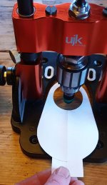
Here goes... I knocked up a rough template based on their measurements: 5 1/4 total length, 2" diameter at the front, guessed at 3/4" dust port overhang and 3" width at the back.
View attachment 1
I then switched to mm, sorry
The distance from chuck centrepoint to the front / back edges of the guide base is approximately 82mm. On my template that has the dust port section emerging from the body of the dust shroud right at the outer edge of the base. These are just rough measurements mind you.
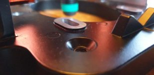
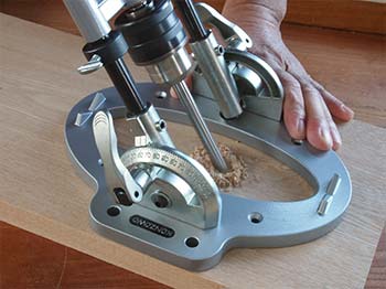
The bad news would be the raised portion on the top side of the base for the self-centering vise (4 slotted holes rising ~2mm) and the round stock guides (2 V shapes rising 8mm). They would interfere with achieving any kind of vacuum.
View attachment 4
View attachment 2
View attachment 3
There would be no problems caused by the height of the dust port.
Some other choice measurements are:
Base outer edge front to back: 168mm
Inside distance between orange rod post holders: 70mm
Aperture opening front to back: 104mm
Aperture opening side to side: 65mm
V guide distance from chuck centre: 67mm to 72mm i.e. they are 5mm thick.
Vise slots measure: 13mm x 23mm
Vise slots are 47mm apart left to right and 62mm front to back.
Keep in mind these measurements were all taken using only a pretty rubbish metal ruler and a good bit of squinting [big grin]
Attachments

[member=53696]Roachmill[/member] - Thank you so much for your most thorough reply!
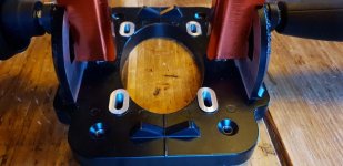
This very telling picture of yours:

...says it all!
Based on it, it's now clear to me that my idea for how to add dust collection to this drill guide is totally doable.
Now, in order to counter your concern over what you characterize as "bad news", I have a different take.
1/4" (6mm) Plexi Overlay
If desired, selecting 1/4" (6mm) thick plexi for construction of the removable overlay will in effect swallow up almost all of the height of each vee guide. Corresponding slots milled through the overlay in the relative locations of the vee guides would serve to essentially eliminate them as obstructions. In the case of the rear vee guide, the remaining ~2mm of it sticking up above the top surface of the overlay would fall within the free area under the shroud (so no conflict there in terms of an obstruction). Now, if needed, a little cap of plexi sized to encapsulate the slot at the rear (with a couple of shallow flat bottomed holes drilled in it to account for the sharp points of the vee guide sitting proud of the top face of the overlay) could be glued in place to hermetically seal the slot. Or (and I'm guessing that this might the case) both vee guide slots in the overlay could simply be left as-is since, practically speaking, I don't think there would enough suction loss at the location of the rear vee guide to warrant any additional effort.
The matter of the four raised cast slots in the base, on the other hand - which are intended for mounting of the vise - could be easily addressed by marking their location on the underside of the overlay and then simply machining corresponding ~2mm deep oval-shaped shallow depressions into the underside of the overlay into which those raised slots would fit (thus allowing the entirety of the overlay to lay perfectly flat and unimpeded onto the top surface of the base).
1/8"(3mm) Plexi Overlay
Alternatively, in order to reduce the amount of milling required to produce said overlay, 1/8" (3mm) plexi could be used instead. If this thinner material will fit underneath the two guide rod pillars (Question: If possible, I need to know the corresponding amount of headroom as depicted below):
View attachment 1
...then this would also potentially greatly simplify the overlay's overall design. But, given the thinner nature of this material, extra care would need to be taken to ensure that the oval depressions milled into its underside (to account for the profiles of the raised slots) don't puncture all of the way through the overlay. If this is a problem, thru-slots could be milled instead and a second duplicate overlay (which omits the slots) could then be stacked on top of (and adhered down onto) the primary overlay. The perimeter of this duplicate overlay could be shaped slightly differently in order to prevent a conflict with the full range of travel of the guide rod pillars while also maintaining enough remaining surface area over the aperture for the shroud to suction down onto. This would bring the overall thickness of the overlay up to a 1/4" (6mm) but that shouldn't be a problem.
On/Off Installation/Removal of Overlay
To facilitate easy on/off of the overlay, countersunk holes and four flat headed screws could be used in conjunction with the threaded holes machined into each corner of the base to allow the installation to be performed from above. Said another way, I didn't realize at first that those countersunk holes in the base are threaded but knowing now that they are would allow the overlay to be fastened down from above. At first, I considered the use of thumbscrews but since, as is shown in your photo, their tall profile would conflict with the rear end of the dust shroud it makes better sense to simply use flush mounted flat-headed screws at all four fastening points. Tool'less installation would be nice but we can't have everything! That said, maybe employing the use of a different suction shroud would ultimately allow the use of four thumbscrews.
Now, if one is going to employ the use of a sub-base (say, in lieu of the guide's problematic non-slip rubber pad), then the four threaded holes won't necessarily be available for use as the attachment method (unless, that is, the length of the fastener chosen allows both the sub-base and the overlay - the latter in conjunction with four threaded inserts - to be co-installed from the underside). However, if this is going to be the case, then to reduce the added-complexity the idea I originally had of utilizing the four cast slots in the base in conjunction with four threaded inserts in the overlay for mounting the overlay from underneath might work better.
Length of Overlay
Finally, its good to know that the rear end of the overlay will not need to be asymmetrically-sized to cantilever-out off the rear end of the drill guide's base all that much. I assumed that it would require quite a bit of overhang but your photo shows that only a little overhang will be necessary.
Thanks again!
This very telling picture of yours:
...says it all!
Based on it, it's now clear to me that my idea for how to add dust collection to this drill guide is totally doable.
Now, in order to counter your concern over what you characterize as "bad news", I have a different take.
1/4" (6mm) Plexi Overlay
If desired, selecting 1/4" (6mm) thick plexi for construction of the removable overlay will in effect swallow up almost all of the height of each vee guide. Corresponding slots milled through the overlay in the relative locations of the vee guides would serve to essentially eliminate them as obstructions. In the case of the rear vee guide, the remaining ~2mm of it sticking up above the top surface of the overlay would fall within the free area under the shroud (so no conflict there in terms of an obstruction). Now, if needed, a little cap of plexi sized to encapsulate the slot at the rear (with a couple of shallow flat bottomed holes drilled in it to account for the sharp points of the vee guide sitting proud of the top face of the overlay) could be glued in place to hermetically seal the slot. Or (and I'm guessing that this might the case) both vee guide slots in the overlay could simply be left as-is since, practically speaking, I don't think there would enough suction loss at the location of the rear vee guide to warrant any additional effort.
The matter of the four raised cast slots in the base, on the other hand - which are intended for mounting of the vise - could be easily addressed by marking their location on the underside of the overlay and then simply machining corresponding ~2mm deep oval-shaped shallow depressions into the underside of the overlay into which those raised slots would fit (thus allowing the entirety of the overlay to lay perfectly flat and unimpeded onto the top surface of the base).
1/8"(3mm) Plexi Overlay
Alternatively, in order to reduce the amount of milling required to produce said overlay, 1/8" (3mm) plexi could be used instead. If this thinner material will fit underneath the two guide rod pillars (Question: If possible, I need to know the corresponding amount of headroom as depicted below):
View attachment 1
...then this would also potentially greatly simplify the overlay's overall design. But, given the thinner nature of this material, extra care would need to be taken to ensure that the oval depressions milled into its underside (to account for the profiles of the raised slots) don't puncture all of the way through the overlay. If this is a problem, thru-slots could be milled instead and a second duplicate overlay (which omits the slots) could then be stacked on top of (and adhered down onto) the primary overlay. The perimeter of this duplicate overlay could be shaped slightly differently in order to prevent a conflict with the full range of travel of the guide rod pillars while also maintaining enough remaining surface area over the aperture for the shroud to suction down onto. This would bring the overall thickness of the overlay up to a 1/4" (6mm) but that shouldn't be a problem.
On/Off Installation/Removal of Overlay
To facilitate easy on/off of the overlay, countersunk holes and four flat headed screws could be used in conjunction with the threaded holes machined into each corner of the base to allow the installation to be performed from above. Said another way, I didn't realize at first that those countersunk holes in the base are threaded but knowing now that they are would allow the overlay to be fastened down from above. At first, I considered the use of thumbscrews but since, as is shown in your photo, their tall profile would conflict with the rear end of the dust shroud it makes better sense to simply use flush mounted flat-headed screws at all four fastening points. Tool'less installation would be nice but we can't have everything! That said, maybe employing the use of a different suction shroud would ultimately allow the use of four thumbscrews.
Now, if one is going to employ the use of a sub-base (say, in lieu of the guide's problematic non-slip rubber pad), then the four threaded holes won't necessarily be available for use as the attachment method (unless, that is, the length of the fastener chosen allows both the sub-base and the overlay - the latter in conjunction with four threaded inserts - to be co-installed from the underside). However, if this is going to be the case, then to reduce the added-complexity the idea I originally had of utilizing the four cast slots in the base in conjunction with four threaded inserts in the overlay for mounting the overlay from underneath might work better.
Length of Overlay
Finally, its good to know that the rear end of the overlay will not need to be asymmetrically-sized to cantilever-out off the rear end of the drill guide's base all that much. I assumed that it would require quite a bit of overhang but your photo shows that only a little overhang will be necessary.
Thanks again!
Attachments

Excellent! Thanks again. That answers all my feasibility questions. Some selective material removal in the region of the pillars will be in order whether 1/4" or 1/8" acrylic is used. That's simple enough.
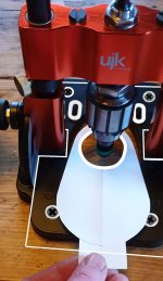
So, for posterity's sake, here are some final mashups, using your image modified to show what an overlay made out of 1/4" (6mm) acrylic might look like:
[attachimg=1]
...and what an overlay made out of a single layer of 1/8" (3mm) acrylic might look like:
[attachimg=2]
I think that either of these would work quite well.
If I don't include the fact that every dust shroud I've found features a round aperture (and not an oval one - which limits the diameter of drill bit that can be used with the shroud in place - this limitation becomes more pronounced as the guide rods are tipped over) the only design limitation I can foresee (at least when a BitBuddie shroud is used - depending on the width of the shroud in use this will be either more or less of a limitation) is when the guide rails are tipped way over. Doing so moves the effective centerline of the chuck forward (relative to the user, deeper into the far narrow end of the aperture in the base) which will necessitate positioning the shroud deeper into the region between the guide rod pillars. This will become a problem the moment the increasingly wider rear end of the shroud is no longer able to fit between the pillars. In this situation one could, I suppose, flip the shroud around to the other side though this may not always be feasible. If one were to instead ensure plenty of overhang on the far side (more than on the near side) then this would address the limitation.
The vee guides prevent the design of the overlay from making use of mounting slots (in place of mounting holes). Slots would be nice since they would allow the overlay to be slid across the base as needed to adjust for the moving centerline of the drill. So, instead, either the opposite end of the overlay needs to be made long enough to account for this situation or the rear end of the overlay needs to be made long enough such that the overlay can be mounted "backwards" in the event that steeply angled holes are desired. Fr this work, the selective removal of material under the pillars would need to accomplished - if possible - without producing a conflict with the location of the shroud. I prefer the idea of making it reversible so will likely adopt that solution myself (meaning, I guess the rear end of the overlay will feature a sizable overhang after all). I'll have to remember that the selective dishing-out of material from the overlay to account for the reduced headroom under the pillars that exists when the guide rods are tipped way over, will need to be accomplished with the overlay positioned in the "backwards" orientation and this will need to be double-checked in advance to make sure that this does set up interference with the ability of the shroud to suction down to the overlay when the overlay is reoriented back to its "forward" position. I won't be able to ascertain whether this is truly a problem until I have both the guide and the shroud in my possession. So, stand by (for a while) for that to happen. Alternatively, it might be worth exploring the feasibility of removing some material from the base of each pillar. Doing so would obviously compromise the anodizing but sometimes sacrifices must be made....
Finally, it occurred to me to simply place some pieces of tape over the oval cutouts (in the case of an 1/8" thick overlay were they to extend all the way through the material) to effectively seal those penetrations. That's a simple method that I bet would do the trick.
Thanks again! Now I'll just to have await patiently for the North American re-release.
So, for posterity's sake, here are some final mashups, using your image modified to show what an overlay made out of 1/4" (6mm) acrylic might look like:
[attachimg=1]
...and what an overlay made out of a single layer of 1/8" (3mm) acrylic might look like:
[attachimg=2]
I think that either of these would work quite well.
If I don't include the fact that every dust shroud I've found features a round aperture (and not an oval one - which limits the diameter of drill bit that can be used with the shroud in place - this limitation becomes more pronounced as the guide rods are tipped over) the only design limitation I can foresee (at least when a BitBuddie shroud is used - depending on the width of the shroud in use this will be either more or less of a limitation) is when the guide rails are tipped way over. Doing so moves the effective centerline of the chuck forward (relative to the user, deeper into the far narrow end of the aperture in the base) which will necessitate positioning the shroud deeper into the region between the guide rod pillars. This will become a problem the moment the increasingly wider rear end of the shroud is no longer able to fit between the pillars. In this situation one could, I suppose, flip the shroud around to the other side though this may not always be feasible. If one were to instead ensure plenty of overhang on the far side (more than on the near side) then this would address the limitation.
The vee guides prevent the design of the overlay from making use of mounting slots (in place of mounting holes). Slots would be nice since they would allow the overlay to be slid across the base as needed to adjust for the moving centerline of the drill. So, instead, either the opposite end of the overlay needs to be made long enough to account for this situation or the rear end of the overlay needs to be made long enough such that the overlay can be mounted "backwards" in the event that steeply angled holes are desired. Fr this work, the selective removal of material under the pillars would need to accomplished - if possible - without producing a conflict with the location of the shroud. I prefer the idea of making it reversible so will likely adopt that solution myself (meaning, I guess the rear end of the overlay will feature a sizable overhang after all). I'll have to remember that the selective dishing-out of material from the overlay to account for the reduced headroom under the pillars that exists when the guide rods are tipped way over, will need to be accomplished with the overlay positioned in the "backwards" orientation and this will need to be double-checked in advance to make sure that this does set up interference with the ability of the shroud to suction down to the overlay when the overlay is reoriented back to its "forward" position. I won't be able to ascertain whether this is truly a problem until I have both the guide and the shroud in my possession. So, stand by (for a while) for that to happen. Alternatively, it might be worth exploring the feasibility of removing some material from the base of each pillar. Doing so would obviously compromise the anodizing but sometimes sacrifices must be made....
Finally, it occurred to me to simply place some pieces of tape over the oval cutouts (in the case of an 1/8" thick overlay were they to extend all the way through the material) to effectively seal those penetrations. That's a simple method that I bet would do the trick.
Thanks again!
Now I'll just to have await patiently for the North American re-release. Attachments

Kanzawa K-801-4 assembly video @5:22 confirms that there is no bushings inside slider 
Delrin sleeve would be a possible improvement but unfortunately the slider collar doesn't extend on the bottom side so there isn't any way to thread the outside to add a sleeve.
Delrin sleeve would be a possible improvement but unfortunately the slider collar doesn't extend on the bottom side so there isn't any way to thread the outside to add a sleeve.
TinyShop said:Also, just stumbled upon another option, this time from Japan. Behold, the very reasonably priced Kanzawa K-801-4, angle-adjustable portable drill stand:


Roachmill
Member
- Joined
- Jun 11, 2015
- Messages
- 297
Newsflash: Axminster have just sent out an email stating the following
Firstly, that's extremely good of them. Secondly, I'm not sure a "very small number" of bases would warrant such blanket action but I'm not going to argue [big grin]
I shall wait and see what the new base is like and update here when appropriate.
We have noticed that a very small number of the UJK Drill Guides have incorrectly machined bases. This has affected how the rubber non-slip pad is supported, resulting in the base not quite sitting flat on the workpiece in some cases. In order to maintain our high product standards and to ensure that you are assured of a product that performs as we expect, we have taken the decision to send you a new base. These bases have been fully and correctly machined here in Axminster.
Firstly, that's extremely good of them. Secondly, I'm not sure a "very small number" of bases would warrant such blanket action but I'm not going to argue [big grin]
I shall wait and see what the new base is like and update here when appropriate.
- Joined
- Feb 22, 2016
- Messages
- 2,858
[member=64030]TinyShop[/member] , I was looking at your proposed dust boot and wondering why it has to completely encompass the bit. I understand that would give the maximum affect but if it only covered the one side then the drill guide would be free to pivot in one direction and I bet your dust collection would still be excellent. Plus faster and easier to attach/remove the dust port. A couple tappings in the base would allow for screws to secure the dust port to the base or maybe a pair of latches similar to the one Festool uses on the OF1400 dust port.
[member=60461]Bob D.[/member] - Good points! I suppose I went the route I did because then I would have a dust shroud that could do double duty. I've held off on acquiring a suction dust shroud (seemed a bit extravagant compared to my current two handed technique - one hand on the drill and the other holding a dust hose) but if I could use one with and without a drill stand then, for me, that makes the purchase of one worthwhile. I guess I needed something to 'push me over the edge' as it were. But, again, your points are well noted.
I guess the quality control issue re: uneven bases has been sorted - just received a notice that the drill guide is back in stock:
https://www.axminster.co.uk/ujk-technology-drill-guide-with-10mm-chuck-106072
https://www.axminster.co.uk/ujk-technology-drill-guide-with-10mm-chuck-106072
Roachmill
Member
- Joined
- Jun 11, 2015
- Messages
- 297
New base arrived today. No visible modifications to the original so I guess they've tried to just use better or proper amounts of glue. It still rocks... but a lot less than the original one did. I'll not be bothering to fit it though.
The design of it is just wrong by virtue of having something flexible fixed to a surface that isn't flat itself. A solid router type base is what it really needs and could so easily have had; but they chose to skimp on it thus rendering it inaccurate which was one of the main selling points :/
Still, the rubber is easy to remove and the metal base is actually flat!
[member=53696]Roachmill[/member] - Hmmmm, interesting. Given that, I encourage you to upload a(nother) review to the Axminster site:
https://www.axminster.co.uk/ujk-technology-drill-guide-with-10mm-chuck-106072
https://www.axminster.co.uk/ujk-technology-drill-guide-with-10mm-chuck-106072
Roachmill
Member
- Joined
- Jun 11, 2015
- Messages
- 297
Done! It may take a few days to appear... they say.TinyShop said:[member=53696]Roachmill[/member] - Hmmmm, interesting. Given that, I encourage you to upload a(nother) review to the Axminster site:
https://www.axminster.co.uk/ujk-technology-drill-guide-with-10mm-chuck-106072
- Joined
- Jun 25, 2016
- Messages
- 466
@rubber ducky - the thread you revived ran before TSO introduced the TSO Parallel Guide. You mention your need / interest in ripping 2.5 inch strips.
Try one of these parallel guides and see how well this works for you and use the return privilege if it does not meet your needs. There are inherent limitations to ripping narrow stock using any parallel guide unless you rarely need that capability.
The TSO Parallel Guide System was designed in response to the shortcomings of the parallel guide we had purchased (one of the brands you are considering) and used it in our own shop and after evaluating the other well known parallel guides, too.
Hans
ElectricFeet
Member
- Joined
- Feb 4, 2017
- Messages
- 302
I wanted a UJK stand (V1) when it first came out (my shop is a cupboard) and luckily missed the window to buy it. After seeing the reviews, I was wary the second time around and the more I think about it, the more I think that the design is not going to work very well -- too many things to go wrong and too few use-cases where you can mitigate the underlying problems.
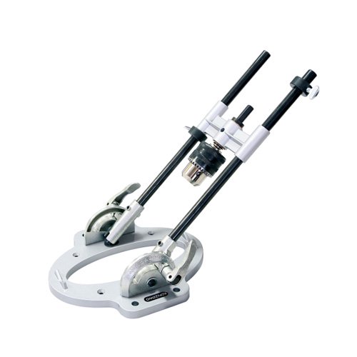
I eventually ordered one of these:

Review here:
It's consumer-level kit (but then, so are the drill stands that are being discussed in the thread). While it takes up considerably more space than a drill stand, it's still much smaller than a traditional drill press and will, crucially, fit in my cupboard -- once I build another cupboard, that is)))
It's only just arrived, so I can't comment on its usability, but it looks sturdy enough. I hate the wheel before even using it though.
I eventually ordered one of these:
Review here:
It's consumer-level kit (but then, so are the drill stands that are being discussed in the thread). While it takes up considerably more space than a drill stand, it's still much smaller than a traditional drill press and will, crucially, fit in my cupboard -- once I build another cupboard, that is
)))It's only just arrived, so I can't comment on its usability, but it looks sturdy enough. I hate the wheel before even using it though.
Roachmill
Member
- Joined
- Jun 11, 2015
- Messages
- 297
That's a fantastic drill for what it is. I saw a lot of praise for it and bought one off the back of that. I don't mind the wheel at all.
I finally got round to making a new base plate for the UJK one out of 9mm MDF I had kicking around. A bit of EPDM stuck on and it's worked a treat making big peg holes in 4x4 oak leg assemblies. Ain't no way they'd fit in my pillar drill
I finally got round to making a new base plate for the UJK one out of 9mm MDF I had kicking around. A bit of EPDM stuck on and it's worked a treat making big peg holes in 4x4 oak leg assemblies. Ain't no way they'd fit in my pillar drill
threesixright
Member
- Joined
- Aug 17, 2017
- Messages
- 629
I think the 1st Bosch also wasn’t without it problems (chuck wobble). But they made it better. There is an after market spoke wheel (not affiliated)https://rover.ebay.com/rover/0/0/0?mpre=https://www.ebay.com/ulk/itm/223895703315ElectricFeet said:It's only just arrived, so I can't comment on its usability, but it looks sturdy enough. I hate the wheel before even using it though.
Similar threads
- Replies
- 6
- Views
- 2K
- Replies
- 21
- Views
- 8K
- Replies
- 2
- Views
- 2K