Festool LR32 - MFT Guide Rail Alignment Jig

Bugsysiegals

Member
Joined
Mar 19, 2016
Messages
908
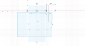
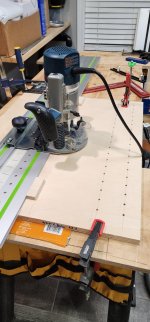
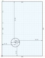
The Festool LR32 works great for drilling 32mm spaced shelf pin holes 37mm from the front edge; however, falls short in easily aligning the guide rail in increments of 32mm from the front edge when drilling drawer slide holes.  After a bit of thought, I designed a little jig which when used in combination with a MFT style table top easily solves this problem and thought I’d share it with you all.

Forewarning, this isn’t the greatest quality, it’s not edited to be quick and to the point, and I know I repeat myself several times (turn the speed up to 1.5x), but I thought it was worth sharing and hopefully it’s of some value to somebody ...


Need measurements of template and layout. I got lost after 32 + 37 = 69 + 3 x 32 = 165

How did you cut plastic template?
 
In the end, this is another option that can work.  I would suggest though that you show the jig in action first and then say "if you like this, hang around to see how it is put together".  I stayed because I am familiar with your posts, and the LR32 is something I want to learn as much about as I can.  But the technical stuff up front might keep some from watching it all.

I know your jig/template is specific to you but if you can post the measurements, it would be a good starting point for us to maybe make one that works for our needs.

I had already ordered the longer hex rod but it hasn't come in yet but your option is appealing once I went through it a couple of times and the light bulb lit up.  I also like not having to secure the rail to the panel.

I like the effort and results, thanks for taking the time to do it.
 
Hi [member=49013]clark_fork[/member] ... I'll do my best to clarify the points you've asked about.

I designed the block in Fusion 360 CAD software and 3D printed it on my $230 Ender 3 Pro.  I absolutely love how I can prototype things in CAD relatively quickly, print them, make revisions, and for most applications have a working copy.  I've never had to have anything sent off to be made in metal but this is just amazing stuff if you're an inventor type.

About the dimensions ... here's the offsets from the 20mm hole and I'm aliasing the sides as A, B, and C for simplicity below.

[attachimg=1]

The setup block allows you to drill holes in increments of 32mm because the MFT holes are in increments of 32mm (32*3) and the 3 sides of the block are in increments of 32mm ... minus a constant (20+18).  I was explaining in the video that you'd want to count the number of 32mm increments needed for your drawer slides in order to determine which MFT row and side of the setup block to use but didn't want to get to deep in the weeds as I know I already talk to much.  If it's still not clear, I've included the table below for reference and highlighted what I used in the video.

[attachimg=2]
 

Attachments

  • LR32 Offset Table2.JPG
    LR32 Offset Table2.JPG
    13 KB · Views: 1,690
  • LR32 Offset Table.JPG
    LR32 Offset Table.JPG
    52.8 KB · Views: 1,773
Rick Herrick said:
In the end, this is another option that can work.  I would suggest though that you show the jig in action first and then say "if you like this, hang around to see how it is put together".  I stayed because I am familiar with your posts, and the LR32 is something I want to learn as much about as I can.  But the technical stuff up front might keep some from watching it all.

I know your jig/template is specific to you but if you can post the measurements, it would be a good starting point for us to maybe make one that works for our needs.

I had already ordered the longer hex rod but it hasn't come in yet but your option is appealing once I went through it a couple of times and the light bulb lit up.  I also like not having to secure the rail to the panel.

I like the effort and results, thanks for taking the time to do it.

I'd considered exactly this approach since I'm one who watches YouTube at 1.5x speed but didn't follow through with it.  I understand quick delivery of information is important, even though I'm not that good at it, so I really appreciate the feedback!

I've shared the dimensions above and you'll notice it will drill ALL 32mm incremented holes + 2mm offset from the front of the panel.  The only thing specific to me is the labels I've added so I don't have to look at the chart or mess things up during my process.

Once I have a moment, I'll add a few additional photos from Fusion 360 and post the model...
[/quote]

Thanks Bugs.  I saw the dimensions you had posted.  I was hopefully looking for the dims of the plastic jig, along with the offset from one corner of your single 20mm ref hole.

BTW, the quality of the video was perfectly fine to me (since you mentioned it may not be up to snuff).  I saw no issues with it at all.
 
Here's my model for the jig.

[attachimg=1]

The bench dog wouldn't fit inside the hole of my first print and rather than tinkering with the flow settings I simply expanded the hole.  Each side is referenced from the center of the circle so that it automatically adjusts when I change the size of the hole and if you remove 10.10mm from each side dimension, the radius, you end up with the numbers I posted above ... (A) 21mm, (B) 53mm, and (C) 85mm.

I've not posted the actual .STL to ThingiVerse as print settings per printer can vary but I could probably modify the drawing and post several iterations with dog hole sizes of 19.90, 20.00, 20.10, and 20.20mm so those of you with a printer can find one that works for your printer.  It's only 5mm thick so it doesn't use very much material to make the jig ... let me know if anybody here has a printer and would like me to upload the .STL.
 

Attachments

  • Capture.JPG
    Capture.JPG
    45.2 KB · Views: 1,788
Rick Herrick said:
In the end, this is another option that can work.  I would suggest though that you show the jig in action first and then say "if you like this, hang around to see how it is put together".  I stayed because I am familiar with your posts, and the LR32 is something I want to learn as much about as I can.  But the technical stuff up front might keep some from watching it all.
the old adage in video for storyline: hope this helps?

1. tell them what you are going to say (intro)
2. Say what you want (main topic points)
3. Tell them what you said ( outro, conclusion, wrap up)
 
I suspect I'll make some more videos at some point so appreciate the feedback! :)

I'm adding another sketch to really help explain how I came up with the 20 and 18 which leaves 21, offset C (smallest side).  From here you could move up another hole and understand how I came up with 53 and 85.

View attachment 1


Attachments

  • Untitled.png
    Untitled.png
    111.9 KB · Views: 441
I really like the idea of the jig. It is even easier than using the TSO parallel guides which is how I am doing it.

I think part of the confusion about the jig is the lack of explanation of the distances related to the guide rail, the LR32 base plate and position of the router center. The dimension that I am not seeing is the distance from the center line of the dog hole behind the rail to the center of the hole drilled by the router. Add this distance to the desired distance from the front edge of the panel and then you can calculate the offsets for the jig.

One of the best parts of the jig, and one thing that the standard use of LR32 doesn't do, is that all distances are referenced from the front of the panel. I work with unbalanced panels and panels that might not have a back parallel to the front. I always reference the front. My first row is using the LR32 bars. Then I write down the current offset on my TSO PG and calculate my stop positions by subtracting the multiple of 32 for the slide holes from the starting offset.
 
Julie said:
I think part of the confusion about the jig is the lack of explanation of the distances related to the guide rail, the LR32 base plate and position of the router center. The dimension that I am not seeing is the distance from the center line of the dog hole behind the rail to the center of the hole drilled by the router. Add this distance to the desired distance from the front edge of the panel and then you can calculate the offsets for the jig.

I posted a diagram in my post above to illustrate the concept and dimensions.  Unfortunately when I post it as expanded the numbers are to small to read so I had to make it expandable so maybe you didn't see it ... check again.  About the distances, you wouldn't measure from the center of the dog hole since the guide rail is aligned to the Right side of the dog hole ... once you see the diagram it should make more sense.

Julie said:
One of the best parts of the jig, and one thing that the standard use of LR32 doesn't do, is that all distances are referenced from the front of the panel. I work with unbalanced panels and panels that might not have a back parallel to the front. I always reference the front. My first row is using the LR32 bars. Then I write down the current offset on my TSO PG and calculate my stop positions by subtracting the multiple of 32 for the slide holes from the starting offset.

"Balanced Panels" are a bit confusing to me as my panels are in dimensions of 32mm; however, since I put my drawer slides at the bottom of the drawers rather than the middle, you couldn't rotate the panel.  In addition, the drawer slides don't have balanced holes so I couldn't flip the slide the other direction and have the holes lined up.  I guess the panel only remains balanced if I drill shelf pin holes.

Before I came up with the idea for the jig I was considering the parallel guides from the rear and it seemed like a process I'd eventually make a mistake with.  In my mind the jig reduces the chance of making a mistake and speeds up the entire process so it will be interesting to see if any of you use it and feel the same.

One thing I noticed in the video was I moving the router from Left to Right which worried me when it snaps into position that it might draw the panel away from the dogs and thus I constantly stop to ensure the panel is aligned.  In the future, I'm going to work from Right to Left so it's dragging the panel into the dogs which may save some time and peace of mind...
 
Was thinking of getting extended bars and buy metric tape.  Here is the issue I face. Any other suggestions?
 

Attachments

  • 20250223_213859.jpg
    20250223_213859.jpg
    321.4 KB · Views: 54
Not sure this helps, but why would anyone want to do it this way? I can understand on very shallow cabinets, where only one additional row of holes is needed, but besides that?

Either way, once into this territory, it is almost sacrilege to not use parallel guides, referencing from the back edge. That us why, IMO, one should just get the plate and forego the small or big LR32 sets, putting that money into the TSO PGs. Peter Millard has an excellent video on this, including how a (proper) accurate end locating thing should look.

Onto the precise way:

If you need more than two "middle" holes, the last thing you want is referencing the "height" position once more.

Instead, place the rail laterally and use the "back" and "front" holes as a reference - need a very simple jig with just 5 (or 8 ) mm pins from a piece of ply to get into the back/front holes and thus locate the rail both laterally and longitudinally.

Now, why does this matter? Well, with that approach one can also make accurate-enough dowel holes for middle fixed shelfs that are structural etc. etc. The only case this is probably too much of a PITA is with just a single addl row of holes for shallow cabinets, there the PGs do shine.
 
Back
Top