ear3
Member
- Joined
- Jul 24, 2014
- Messages
- 4,341
So over the next month, I'm going to be building a film set, which will then be struck and reinstalled in a museum/gallery space in mid August. Because I'm ordinarily very bad at documenting my own professional work, I wanted to use this forum as a chance to chronicle the build and establish a record I can look back at later.
The movie is an "art" film. It's non-narrative but will instead consist of a series of vignettes where the focus is primarily the set and embedded images (and the accompanying music/sound) , rather than the people who might populate that particular part of the set. This actually places a premium on the work that I'm doing, since it will be the main focus of the viewer. The artists, one of whom I've been building for since 2004, have previously done large installations that were cinematic in nature, and so the move over to movies was kind of a natural thing. My contribution is going to be two-fold. I'm building the basic architecture of the set, which will then be arranged and decorated by the production design team. After that's in place I'm in charge of doing the build of one of the main room's, which will be a courtroom, and so will be woodworking heavy.
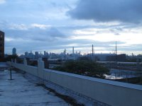
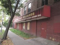
We snagged a suitably large and creepy place for the shoot in Queens on the border between a residential and a warehouse district. It used to be a Billiards Club (ground floor)/Martial Arts and Boxing Gym (second floor, where I'm doing most of the assembly and cutting). This is what it looks like from the outside:
[attachthumb=1]
[attachthumb=2]
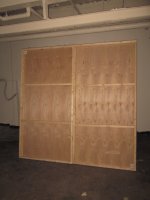
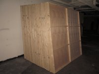
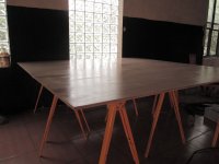
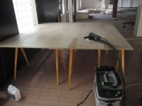
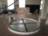
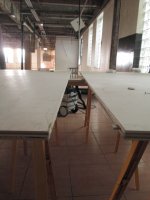
The inside has been gutted out, and so is perfect for constructing the set. The smell is weird -- think a locker room that was never cleaned but hasn't been used in a couple of years --, but the music from my Milwaukee radio/charger sounds excellent in the cavernous space:
[attachthumb=3]
[attachthumb=4]
[attachthumb=5]
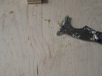
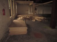
Remnants of the old gym, which I'm going to promote into being my official men-at-work sign:
[attachthumb=6]
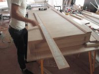
I had already gone to the BORG and snagged the framing timber for the flats. Since we're using 2x3s, I had to hand select every one of 400 boards for straightness, and so today we got some help to bring them, along with 100 sheets of luan, up the 65 foot ramp to the second floor:
[attachthumb=7]
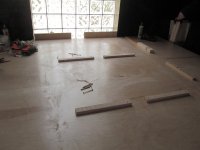
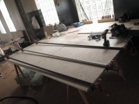
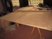
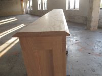
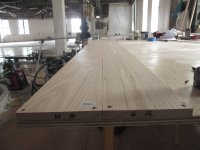
My goal today was just to setup my work table so I can get going early tomorrow when I bring over the rest of my tools. I chose to set up right behind the old gym showers, because there's still tile in that area which provides an even, level surface:
[attachthumb=9]
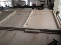
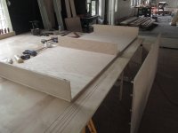
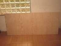
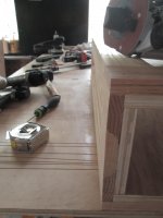
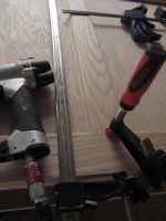
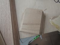
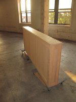
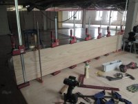
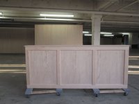
Got 2 sheets of maple veneered plywood for the work table (I actually paid for Birch, but the BORG folks threw these on top of all the luan sheets, so I didn't complain). To make it tight, I put some 5mm dominoes in to align the boards:
[attachthumb=8]
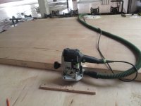
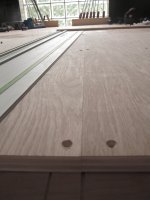
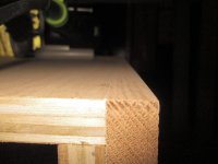
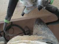
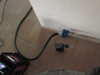
And then used pocket screws to draw them together -- thanks BTW FOG for the suggestion on the 1 1/4" PVC elbow to mate the 27mm hose with the K4 dust attachment
[attachthumb=10]
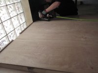
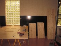
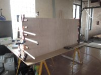
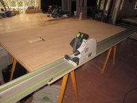
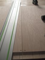
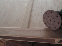
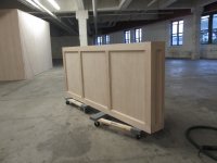
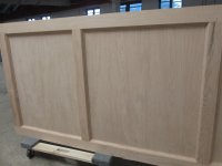
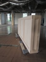
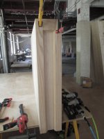
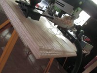
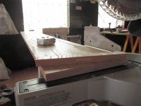
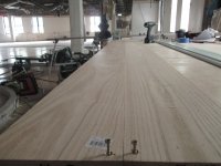
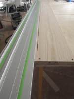
Following some additional good advice I got on the FOG, I slapped a couple of coats of quick dry poly on the sheets to make glue removal easier, sanding in between coats with the RO150 at 320 :
[attachthumb=11]
[attachthumb=12]
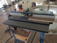
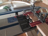
The first part of the build is more drudgery than anything else, but I'm hoping the recent acquisition of the Kapex and UG cart can speed things up by helping automate all the repeatable cuts I have to do. More in the coming days.
The movie is an "art" film. It's non-narrative but will instead consist of a series of vignettes where the focus is primarily the set and embedded images (and the accompanying music/sound) , rather than the people who might populate that particular part of the set. This actually places a premium on the work that I'm doing, since it will be the main focus of the viewer. The artists, one of whom I've been building for since 2004, have previously done large installations that were cinematic in nature, and so the move over to movies was kind of a natural thing. My contribution is going to be two-fold. I'm building the basic architecture of the set, which will then be arranged and decorated by the production design team. After that's in place I'm in charge of doing the build of one of the main room's, which will be a courtroom, and so will be woodworking heavy.
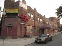
We snagged a suitably large and creepy place for the shoot in Queens on the border between a residential and a warehouse district. It used to be a Billiards Club (ground floor)/Martial Arts and Boxing Gym (second floor, where I'm doing most of the assembly and cutting). This is what it looks like from the outside:
[attachthumb=1]
[attachthumb=2]
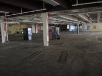
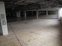
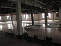
The inside has been gutted out, and so is perfect for constructing the set. The smell is weird -- think a locker room that was never cleaned but hasn't been used in a couple of years --, but the music from my Milwaukee radio/charger sounds excellent in the cavernous space:
[attachthumb=3]
[attachthumb=4]
[attachthumb=5]
Remnants of the old gym, which I'm going to promote into being my official men-at-work sign:
[attachthumb=6]
I had already gone to the BORG and snagged the framing timber for the flats. Since we're using 2x3s, I had to hand select every one of 400 boards for straightness, and so today we got some help to bring them, along with 100 sheets of luan, up the 65 foot ramp to the second floor:
[attachthumb=7]
My goal today was just to setup my work table so I can get going early tomorrow when I bring over the rest of my tools. I chose to set up right behind the old gym showers, because there's still tile in that area which provides an even, level surface:
[attachthumb=9]
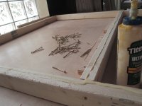
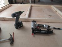
Got 2 sheets of maple veneered plywood for the work table (I actually paid for Birch, but the BORG folks threw these on top of all the luan sheets, so I didn't complain). To make it tight, I put some 5mm dominoes in to align the boards:
[attachthumb=8]
And then used pocket screws to draw them together -- thanks BTW FOG for the suggestion on the 1 1/4" PVC elbow to mate the 27mm hose with the K4 dust attachment
[attachthumb=10]
Following some additional good advice I got on the FOG, I slapped a couple of coats of quick dry poly on the sheets to make glue removal easier, sanding in between coats with the RO150 at 320 :
[attachthumb=11]
[attachthumb=12]
The first part of the build is more drudgery than anything else, but I'm hoping the recent acquisition of the Kapex and UG cart can speed things up by helping automate all the repeatable cuts I have to do. More in the coming days.
Attachments
-
 IMG_5178.JPG3.4 MB · Views: 560
 -
 IMG_5177.JPG2.4 MB · Views: 456
 -
 IMG_5175.JPG2.6 MB · Views: 452
 -
 IMG_5169.JPG2.6 MB · Views: 479
 -
 IMG_5168.JPG2.9 MB · Views: 523
 -
 IMG_5172.JPG2.6 MB · Views: 470
 -
 IMG_5160.JPG2.5 MB · Views: 435
 -
 IMG_5159.JPG2.5 MB · Views: 439
 -
 IMG_5164.JPG2.7 MB · Views: 386
 -
 IMG_5157.JPG2.9 MB · Views: 366
 -
 IMG_5156.JPG2.6 MB · Views: 478
 -
 IMG_5179.JPG2.9 MB · Views: 473