ear3
Member
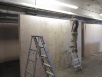
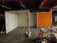
So when I came in yesterday I was told that actually the total number of flats had been miscalculated, and that we needed another 25. As I was inspecting the ceiling pipes to find which one would be the best over which to swing a rope and hang myself, the art director came back and reported that actually, we were only 11 flats short. So not so bad -- a half a day's extra work, but I'm really not looking forward to reverting to flat building after I thought I was done with it. I've left it for when I go back onsite on Wednesday, and instead focused on starting the structure of the judge's bench and witness stand.
This part will be a real challenge. I've never built anything like this, meaning, something that has to look tight and authentic AND be modular/disassemble-able. Here's the (literal) back of the envelope sketch I'm working with in my head (though obviously it will be finished with paneling and moulding):
[attachthumb=1]
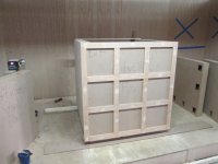
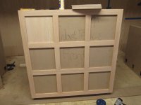
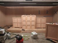
So I think the best way to proceed is to break the structure up into individual MDF boxes, which will be joined together and then have pre-made panels fitted on top of their face. The MDF box structure will be like so:
[attachthumb=2]
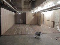
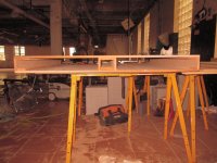
I'm having the other carpenters build a 8" platform for everything to rest on so I can have a level surface to work with.
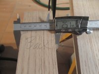
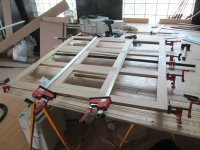
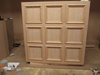
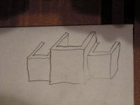
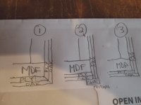
The tricky thing will be how to attach the panels together, which I will pre-assemble from 1/2" oak veneer ply with a 1x3 and inset moulding oak frame. I think mitering on the flat (option 1) is out of the question, as there are two many things that could go wrong and I can't tie the joint together so much that it can't be disassembled. So I originally thought about running the side panels long and have the front ones butt up against them, then hide the joint with an additional piece of case moulding (option 2). Now I'm thinking though that I can build them so that they are stepped/rabbeted, and so fit together more snugly (option 3), and simply use clamps and the force of the screws attaching the panels into the MDF to secure a reasonably tight joint (option 3). Here's how I've drawn out the three options:
[attachimg=3]
If anyone has any better ideas I would love to hear them.
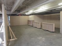
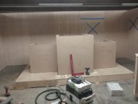
So I went to work yesterday on assembling the boxes. It's been a long time since I worked with MDF as a structural element (as opposed to a shelf or a, say, a top for my workbench). So I had to dig way back to my early days working in museums and galleries as an installer, trying to remember how we put all those pedestals and display cases for the artwork together. One of the cool things about MDF is the way you can integrate all the scrap and offcuts as supports.
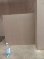
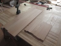
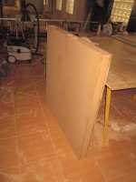
So I started by making two large rectangles:
[attachthumb=4]
Using glue and pneumatic staples I then added a strip down the middle at the same place on the interior of both rectangles for the two verticals to attach to:
[attachthumb=5]
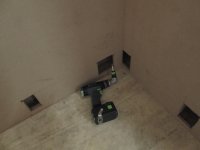
Then did the same thing along the sides, and attached the outer verticals to the other rectangle. Fortunately you know that with MDF the size of your spacer block is the size of your actual piece, so it's just a question of getting the spacer block flush:
[attachthumb=6]
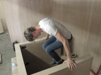
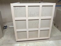
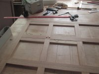
Then put the two rectangles together with more glue and staples:
[attachthumb=7]
[attachthumb=8]
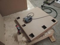
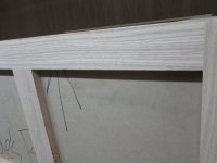
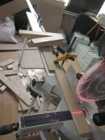
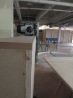
Added a top and bottom and routed it flush with the 1010:
[attachthumb=9]
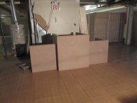
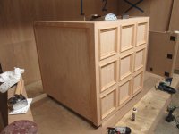
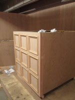
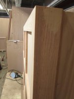
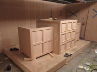
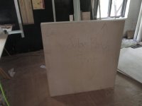
And we have our first of seven boxes -- I'll probably do some cut outs later for hand holds and for access points to secure the boxes to the floor and to one another:
[attachthumb=10]
This part will be a real challenge. I've never built anything like this, meaning, something that has to look tight and authentic AND be modular/disassemble-able. Here's the (literal) back of the envelope sketch I'm working with in my head (though obviously it will be finished with paneling and moulding):
[attachthumb=1]
So I think the best way to proceed is to break the structure up into individual MDF boxes, which will be joined together and then have pre-made panels fitted on top of their face. The MDF box structure will be like so:
[attachthumb=2]
I'm having the other carpenters build a 8" platform for everything to rest on so I can have a level surface to work with.
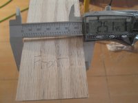
The tricky thing will be how to attach the panels together, which I will pre-assemble from 1/2" oak veneer ply with a 1x3 and inset moulding oak frame. I think mitering on the flat (option 1) is out of the question, as there are two many things that could go wrong and I can't tie the joint together so much that it can't be disassembled. So I originally thought about running the side panels long and have the front ones butt up against them, then hide the joint with an additional piece of case moulding (option 2). Now I'm thinking though that I can build them so that they are stepped/rabbeted, and so fit together more snugly (option 3), and simply use clamps and the force of the screws attaching the panels into the MDF to secure a reasonably tight joint (option 3). Here's how I've drawn out the three options:
[attachimg=3]
If anyone has any better ideas I would love to hear them.
So I went to work yesterday on assembling the boxes. It's been a long time since I worked with MDF as a structural element (as opposed to a shelf or a, say, a top for my workbench). So I had to dig way back to my early days working in museums and galleries as an installer, trying to remember how we put all those pedestals and display cases for the artwork together. One of the cool things about MDF is the way you can integrate all the scrap and offcuts as supports.
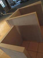
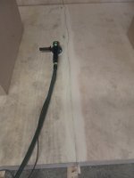
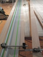
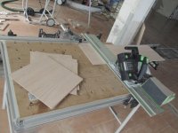
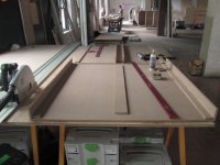
So I started by making two large rectangles:
[attachthumb=4]
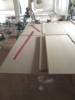
Using glue and pneumatic staples I then added a strip down the middle at the same place on the interior of both rectangles for the two verticals to attach to:
[attachthumb=5]
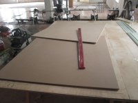
Then did the same thing along the sides, and attached the outer verticals to the other rectangle. Fortunately you know that with MDF the size of your spacer block is the size of your actual piece, so it's just a question of getting the spacer block flush:
[attachthumb=6]
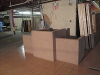
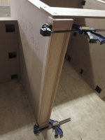
Then put the two rectangles together with more glue and staples:
[attachthumb=7]
[attachthumb=8]
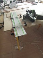
Added a top and bottom and routed it flush with the 1010:
[attachthumb=9]
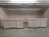
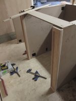
And we have our first of seven boxes -- I'll probably do some cut outs later for hand holds and for access points to secure the boxes to the floor and to one another:
[attachthumb=10]
Attachments
-
 IMG_5346.JPG2.5 MB · Views: 286
 -
 IMG_5344.JPG2.5 MB · Views: 294
 -
 IMG_5343.JPG2.6 MB · Views: 262
 -
 IMG_5339.JPG3 MB · Views: 266
 -
 IMG_5338.JPG2.9 MB · Views: 253
 -
 IMG_5336.JPG2.8 MB · Views: 301
 -
 IMG_5335.JPG2.5 MB · Views: 259
 -
 IMG_5334.JPG2.7 MB · Views: 243
 -
 IMG_5348.JPG2.6 MB · Views: 1,833
 -
 IMG_5347.JPG2.7 MB · Views: 272