Film set/Art Installation build [updated 8.26.15]

Since there was a lot more going on than just the courtoom, here's a few pictures of some of the other scenes in various states of being built/filmed:

[attachthumb=1]

[attachthumb=2]

[attachthumb=3]

[attachthumb=4]

[attachthumb=5]

[attachthumb=7]

[attachthumb=8]

[attachthumb=9]

[attachthumb=6]
 

Attachments

  • IMG_5687.JPG
    IMG_5687.JPG
    459.4 KB · Views: 254
  • IMG_5643.JPG
    IMG_5643.JPG
    427.3 KB · Views: 222
  • IMG_5641.JPG
    IMG_5641.JPG
    534 KB · Views: 236
  • IMG_5707.JPG
    IMG_5707.JPG
    2.5 MB · Views: 272
  • IMG_5702.JPG
    IMG_5702.JPG
    404.1 KB · Views: 218
  • IMG_5700.JPG
    IMG_5700.JPG
    481.2 KB · Views: 224
  • IMG_5697.JPG
    IMG_5697.JPG
    498.3 KB · Views: 230
  • IMG_5692.JPG
    IMG_5692.JPG
    448.1 KB · Views: 215
  • IMG_5690.JPG
    IMG_5690.JPG
    593.7 KB · Views: 239
[member=44099]Cheese[/member] Thanks -- I was pleasantly surprised as well with how straightforward the coping foot turned out to be.  Having never jigsawed my copes, I was worried about cutting into the profile with something so aggressive, but my worries proved unfounded. 

Yeah, I've got a backlog of photos that I'm going to be posting, including a pretty incredible set of pics from moving the judge's bench down several flights of stairs and destroying part of a wall to get it through a door!

Cheese said:
Nice stuff Edward...interesting that the learning curve for the Collins foot wasn't very steep. [big grin]

Are you going to share some photos of the reinstall segment?

[member=37411]Edward A Reno III[/member]
 
Some rather interesting Law Journals that the judge is reading. [huh]
 
This is slightly out of chronological order, but as it forms a self-contained series I've decided to post it.  Again, I'm trying to change my poor documentation habits and instead compile a thorough record of my work, so that I can go back to it later.  Also, I'm surprisingly bad at remembering my own learning process -- it's difficult for me to think back to a time when I didn't know certain things, so having this record is also a way for me to document the ongoing evolution of my approach to carpentry.

I should have heeded the admonition of [member=44099]Cheese[/member] more carefully when he asked whether all the dimensions were in order for the move/reinstallation.  Everything was in order to get the judge's bench -- disassembled into three components -- onto and off of the freight elevator over at Red Bull Studios.  But the person who gave me the measurements forgot to mention that the hallway leading out from the elevator in the basement, where the courtroom is being reinstalled, has a turn that narrows to less than the width of the central bench unit.  Don't ask me why you would build a narrow hallway out of a freight elevator, but that's the way it is.  Just a reminder that you need to do everything yourself to be certain.

So when I arrived at the gallery the bench unit was sitting in the foyer abandoned and forlorn:

[attachthumb=1]

You'll notice that steep flight of steps to the basement, which I initially understood to be the only other way to get the bench down:

[attachthumb=2]

My initial plan was to use gravity as our friend.  The bench was just wide enough so that it would sit on the handrails, and so I figured we could wrap it up in blankets, attach a bunch of ropes and/or webbing, including using the overhead pully for some leverage, brace the handrails with 2x4s, and trust in God that no one got killed -- but film the whole thing just in case so we could at least get a Youtube Epic Fail moment out of it.  The problem was the initial lift onto the rails and the sudden, steep drop.  I didn't weigh it, but I would put it at about 350 pounds, exacerbated by the size and awkward shape.  That initial downward shift was fraught with danger.

Keep in mind that this was in no ways part of my commission, and that all the moving was supposed to be done by the contractors we hired, but they kept on delaying, hoping I would cut the thing into pieces and so spare them the possibility of injury (which I totally understand), but I was pretty insistent that we at least give it a try, and so I had to oversee the process.  Fortunately, there was onsite a contractor with a lot more experience in art handling/installation than I, and he graciously more or less assumed the role as project manager on the bench move (thanks Shan!).

So the bench sat there all last week while everyone waited for someone else to say it was time to move it, with everyone wanting to postpone injury and death as long as possible.  But two days ago we found out about another staircase to the basement, one with more flights but not as steep a drop, and so we decided to go for it there.

[attachthumb=4]

[attachthumb=5]

So Shan oversaw outfitting the bench with skids and 2x4s so that it could be carried essentially like the Ark of the Covenant, with the 2x4s resting on people's shoulders:

[attachthumb=3]

With about 7 guys, we managed to get the bench down to the bottom, removing and reattaching the 2x4 poles as necessary to make the turns:

[attachthumb=6]

It was when we tried to get it out the last doorway that we ran into a problem.  The walls on the other side came out from the door frame a foot or so, and thus did not have enough clearance for the bench.  At one point trying to jam the thing through one of the miters on the top cracked, causing me to scream out in pain as if someone had just stuck a knife in my stomach:

[attachthumb=8]

We had removed the brace holding the two sides together to angle it around the door frame, and so we quickly reinstalled it and tried to strategize how to complete the move

[attachthumb=7]

Realizing the wall to the right of the door was just a few layers of drywall, we decided to sacrifice this to the cause.  The gallery managers watched with increasing horror as we demoed the corner to make way for the bench.  Good thing I had brought my cordless angle grinder and Fein multimaster:

[attachthumb=9]

[attachthumb=10]

[attachthumb=11]

[attachthumb=12]

In the end we made it through, depositing the bench on the platform.  Lots of bangs and nicks that needed to be repaired, but with the LS130 I was able to perform a minor restoration miracle yesterday, about which I'll post later.


Attachments

  • IMG_5796.JPG
    IMG_5796.JPG
    388.7 KB · Views: 189
  • IMG_5797.JPG
    IMG_5797.JPG
    416.3 KB · Views: 210
  • IMG_5798.JPG
    IMG_5798.JPG
    426 KB · Views: 196
  • IMG_5800.JPG
    IMG_5800.JPG
    409 KB · Views: 216
  • IMG_5813.JPG
    IMG_5813.JPG
    440.3 KB · Views: 246
  • IMG_5815.JPG
    IMG_5815.JPG
    442.4 KB · Views: 188
  • IMG_5795.JPG
    IMG_5795.JPG
    436 KB · Views: 210
  • IMG_5794.JPG
    IMG_5794.JPG
    495.5 KB · Views: 213
  • IMG_5718.JPG
    IMG_5718.JPG
    2.4 MB · Views: 238
  • IMG_5717.JPG
    IMG_5717.JPG
    2.5 MB · Views: 213
  • IMG_5791.JPG
    IMG_5791.JPG
    388.2 KB · Views: 186
  • IMG_5792.JPG
    IMG_5792.JPG
    468 KB · Views: 194
  • IMG_5793.JPG
    IMG_5793.JPG
    469.7 KB · Views: 168
Edward,
Thanks so much for the considerable effort in documenting this build, made more remarkable by the tight time constraints. I found it very interesting as well as educational. I think the preparation behind the scenes of a film set are a little understood and highly entertaining subject. If you ever travel north to the Adirondacks, I owe you a drink!
-Charlie
 
Thanks man.  Will definitely give you a buzz next time I'm there.  Likewise if you're ever in NYC.

Charlie Mac said:
Edward,
Thanks so much for the considerable effort in documenting this build, made more remarkable by the tight time constraints. I found it very interesting as well as educational. I think the preparation behind the scenes of a film set are a little understood and highly entertaining subject. If you ever travel north to the Adirondacks, I owe you a drink!
-Charlie
 
Just a small update on the restoration of the judge's bench.

So the process of moving the bench out from Queens, and especially getting it down the stairs and through the door at the art gallery, was very traumatic for the bench.  The face and sides were fortunately unharmed, but the top was a real mess, especially the right corner:

[attachthumb=1]

So I finally got to use the LS130 on the project, which has otherwise been living at the bottom of the stack of systainers all month:

[attachthumb=2]

Using the full range of profile pads, I worked it down until the gouge was minimal.  I had to destroy part of the profile in the process, but I think the trade off is worth it, and few will notice the difference:

[attachthumb=3]

[attachthumb=4]

[attachthumb=5]

I'm sure it would be possible to recut that erased profile line with the proper hand tools, but that is beyond my skill level and tooling.  I made a pass with the sander over the rough spots elsewhere on the bench and applied another coat of Osmo:

[attachthumb=6]

And now the bench is feeling pretty fine:

[attachthumb=7]

[attachthumb=8]
 

Attachments

  • IMG_5827.JPG
    IMG_5827.JPG
    448 KB · Views: 173
  • IMG_5826.JPG
    IMG_5826.JPG
    434.7 KB · Views: 168
  • IMG_5822.JPG
    IMG_5822.JPG
    440.2 KB · Views: 175
  • IMG_5821.JPG
    IMG_5821.JPG
    403 KB · Views: 193
  • IMG_5820.JPG
    IMG_5820.JPG
    428.6 KB · Views: 191
  • IMG_5819.JPG
    IMG_5819.JPG
    403.3 KB · Views: 194
  • IMG_5816.JPG
    IMG_5816.JPG
    428.9 KB · Views: 205
  • IMG_5814.JPG
    IMG_5814.JPG
    434.2 KB · Views: 206
Nice recovery.  I might have tried the saw and rail to cut back the outside by 1/4" on the three outside edges and then re-route the same profile as you had.

But you did a remarkable job!

Thanks for sharing this endeavor from planning through completion.  I learned a lot about set construction!

Neil
 
I apologize if the last few posts have been more show and tell than build/tool focused.  I should more than make up for it with this post, however.

The ostensible reason why I was asked to come over to the gallery and continue the build was to figure out what to do with the two pillars that were smack in the middle of the space where the courtroom was relocated:

[attachthumb=1]

[attachthumb=14]

The artists suggested a square cover, but concerned about how far they would jut out into the space -- and also desiring to take on a challenge -- I proposed building an octagonal one.  I had never really done something like this before, that is, a large, more than 4 sided polygon structure, but I figured it was just about getting the math right, and that the Festool and Woodpeckers precision would take care of the rest.

So it was off to Boards and Beams in NJ to restock on lumber.  As I remarked in a precious post, this place is a wood lovers Nirvana, and now I've got the pictures to prove it:

[attachthumb=2]

[attachthumb=3]

[attachthumb=4]

That overhead loft is up where I again clambered to get all the red oak moulding.  I decided to make the panels for the octagons using 1x pine covered with 1/4 RO veneered ply, so I got a bunch of 1x12 pine to rip the rails and stiles of the frames:

[attachthumb=5]

Not only is ripping a cheaper proposition than just getting individual 1x3 pine boards -- $1.50/ft. for the 1x12, so it was the equivalent of .30 a ft. since I was able to rip 5 two in. boards from a single 1x12 (that makes it the same price as a 2x4!) -- it also better ensures a straight board when ripped with the track saw.  I think if I ever do a theater flat project again, this is the way I will go, as those 2x3 frames were a nuisance to get square and to join together once assembled.   

Back at Red Bull studios I set up my new work station, recycling one of the 3/4" sheets of maple ply I had used over at the warehouse in Queens.  Much happier to have an air conditioned and well lit space this time around, and the bright white backdrop almost made me feel like I was doing a Festool commercial [big grin]:

[attachthumb=6]

[attachthumb=7]

You'll see among the gear my new Systainer handled toolbox, which I picked up after getting frustrated about having essential tools (hammer, pliers, angle grinder) scattered all over the place back at the Queens space.

First things first, I ripped down all the pine boards using the LR32 edge stops, which is what I had done over in Queens when ripping the battens from the 1x12 oak boards:

[attachthumb=8]

[attachthumb=10]

Having gotten tired of the power cord getting yanked out of the CT, but not really interested in the boom arm, before the build I had modified the setup to have a short three outlet extension run from the CT and then zip tied the cord to the vac hose:

[attachthumb=9]

Much happier with this arrangement, since it also allows for additional cords to run through the CT, so this will be me default setup going forward.

After cutting the pine frame members on the Kapex, I then ripped the plywood to a rough size and attached the frame members to it directly (stiles first, then rails) with the pneumatic stapler and some wood glue:

[attachthumb=11]

[attachthumb=12]

[attachthumb=13]

Two points on this.  First, there was no need to join the frame members to one another via domino or pocket hole screw, as the octagon was not going to be load bearing.  Second, I fortunately thought ahead and marked off, as you can see with the arrow in the last picture, where the dominos would be placed to attach the panels to one another.  This ensured that when I mortised the panels I would not be hitting any staples.

Rinse.  Wash.  Repeat 8 times until I had all the panels for one octagon:

[attachthumb=15]

I'll continue this in the next post. 


Attachments

  • IMG_5730.JPG
    IMG_5730.JPG
    406 KB · Views: 159
  • IMG_5739.JPG
    IMG_5739.JPG
    473 KB · Views: 160
  • IMG_5733.JPG
    IMG_5733.JPG
    472.9 KB · Views: 173
  • IMG_5737.JPG
    IMG_5737.JPG
    481.6 KB · Views: 166
  • IMG_5753.JPG
    IMG_5753.JPG
    440.2 KB · Views: 190
  • IMG_5742.JPG
    IMG_5742.JPG
    421.1 KB · Views: 169
  • IMG_5734.JPG
    IMG_5734.JPG
    469.1 KB · Views: 180
  • IMG_5729.JPG
    IMG_5729.JPG
    457 KB · Views: 171
  • IMG_5728.JPG
    IMG_5728.JPG
    431 KB · Views: 169
  • IMG_5726.JPG
    IMG_5726.JPG
    410.8 KB · Views: 179
  • IMG_5722.JPG
    IMG_5722.JPG
    693.9 KB · Views: 208
  • IMG_5723.JPG
    IMG_5723.JPG
    610.4 KB · Views: 205
  • IMG_5720.JPG
    IMG_5720.JPG
    2.6 MB · Views: 181
  • IMG_5724.JPG
    IMG_5724.JPG
    442.7 KB · Views: 193
  • IMG_5727.JPG
    IMG_5727.JPG
    463.6 KB · Views: 174
The next step is where the Festool and Woodpeckers (and Incra and Seneca!) precision comes into play.

Let me just take a step back for a second and say that this particular build could be a case study for how Festool has changed my approach to carpentry.  Two things in particular:

1.  The importance of repeatable measurements, as opposed to precise measurements.  I've remarked on this before, but one of the things that was a revelation to me when I discovered it was how the exact measurements of what you build are often not as important as those measurements being consistent throughout the structure, i.e., it makes no difference if you're box is 18" of 18 and 53/64", just as long as all the sides are the same length.  I kind of understood this before Festool, but it was using Festool that allowed me to really put this into practice, and I'm constantly learning more ways in which I can employ this principle.  And it was in some ways counter to how I had practiced carpentry up to that point, where I had spent a lot of time and effort learning how to make precise measurements.  Not that the ability to measure precisely isn't still essential, but it's no longer the cornerstone I understood it to be.

2. Sort of a corollary of the first, but the idea of building rough and then cutting it straight/square, as opposed to getting everything straight/square right from the start.  As you'll see with the octagon, this is really the only way it could be built, especially since I didn't have a table saw on hand.

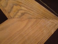
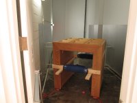
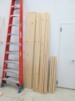
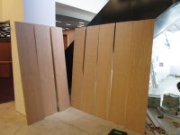
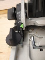
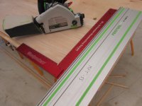
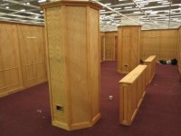
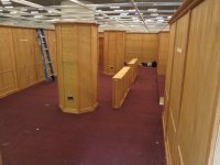
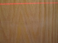
So back to the build.  The diameter of the pillar was 36".  This meant a minimum interior side length for the octagon of about 15 1/4".  To give myself some breathing room, I planned on 16 3/4", which meant that I would actually set the measurement around 17 1/2" to account for the 1" thickness of the pine frame and oak ply.  So I made each panel a rough size of 18", allowing for 1/4" of trimming on both sides.  So after setting the TS75 bevel to 22.5 degrees, the appropriate angle for a regular octagon:

[attachthumb=1]

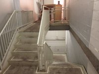
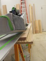
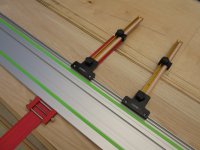
I trimmed one side of each of the panels.  I then pulled out the Seneca parallel guides and Woodpeckers ruler with rule stop, which, thanks to [member=18283]RLJ-Atl[/member] I learned was the most precise way to set the guides: http://festoolownersgroup.com/festool-how-to/rule-with-stop-to-set-parallel-guides/msg285508/#msg285508

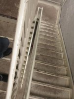
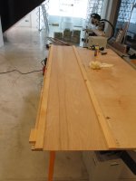
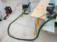
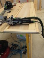
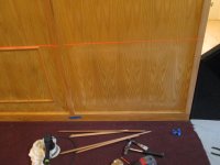
I had gotten the Seneca guides for the earlier part of the build, but for whatever reason never actually used them.  It was a revelation when I set them up though, and my only regret is not having gotten them a year ago.  To minimize any chance of miscalibration, I had already reset/recut the splinter guide on the 3000mm rail, and then just to be safe, I set the guides in the exact same spot on the track, and furthermore, positioned them a couple of inches shy of the front and back, since with bevel cuts there is sometimes the danger of a slight deflection on entry and exit because there is nothing supporting the rail:

[attachthumb=2]

[attachthumb=3]

This deflection can be avoided, of course, if you support the rail at either end with scrap, but this was not possible with my setup and because I was doing 8 ft. long rips.

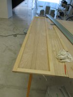
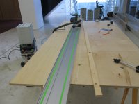
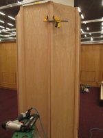
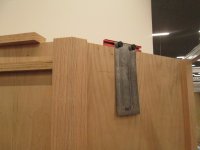
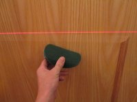
After I ripped the panels to width -- and they were all the exact same width thanks to the guides and ruler -- I then used the TSC55 to square the ends, bottom first then top, just using the Woodpeckers 26" framing square that I recently got thanks to another FOG member.  Having another saw was nice, as it meant I didn't have to reset the bevel on the TS75, just in case I had to redo a panel (ultimately didn't have to, but it was good to have this safety net):

[attachthumb=4]

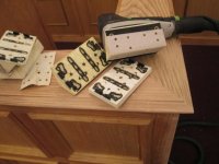
Once the panels were all sized, I busted out the Domino, set the fence to 22.5, and did the mortises, spacing them one every foot (total of 18 per panel):

[attachthumb=5]

I initially did 4mm dominos, because I figured it would be enough for a non load bearing structure, and also because I was looking for a reason to work down the stockpile of a size I don't use that often:

But after dry fitting the parts I realized I needed a longer tenon to make it work, so I redid them all at 5mm.  Here I learned one advantage of not having to put your tools away at night, since I could just grab the machine the next day and have the fence settings be exactly the same.

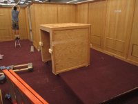
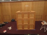
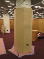
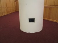
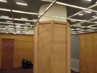
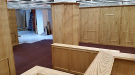
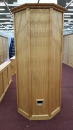
After I made sure all the parts fit together around the pillar and had sufficient clearance:

[attachthumb=6]

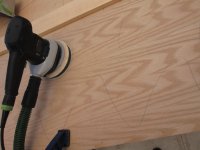
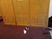
I did the cutouts for the electrical outlets with the Carvex, and sanded the panels at 150 grit with the ETS150/3 and soft pad, having to switch occasionally over to the interface pad because some of the veneer was burning even with this sander (cheap ply!):

[attachthumb=7]

[attachthumb=8]

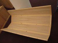
For the glue up, I assembled the units in two parts made up of 4 sides:

[attachthumb=9]

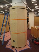
Then used a pair each of Bessey and Pony strap clamps to bring it together:

[attachthumb=10]

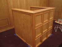
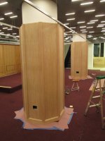
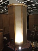
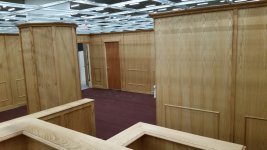
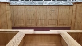
The resulting structure turned out pretty tight:

[attachthumb=11]

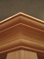
There were still slight gaps in some of the joints, but that was fine since I was going to be finishing them off with oak trim.

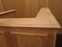
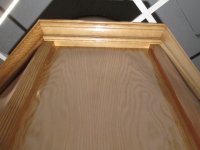
For the trim, I first put in the 1x4 baseboard, then ripped down 1x12 oak boards using the TS75 and TSC55 in combination on the 3000mm rail, again, so I didn't have to reset the bevel on the 75:

[attachthumb=12]

Doing it this way also ensured a perfect fit, since for each pair of boards I simply flipped one of them over to get the proper angle.

EDIT: I should note, however, that at one point I switched the angle to 22.7 or .8, since on one of the test fits I found a tiny gap in the adjoining battens, due no doubt to the varying clamping pressure on such thin panels.  Thereafter I kept the TS75 at the slightly sharper angle, figuring it wouldn't hurt to overshoot the miter even on the sides that were true 45 (or 135) degree angles.  But it was an important lesson that for this stage of the build, it was good to work piece by piece, rather than cutting everything beforehand.
 
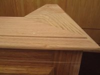
Using a combination of small trigger clamps, glue, an 18 gauge nailer (to secure the trim to the structure) and a 23 gauge pin nailer (to keep the joint closed), I then worked my way down each pair to get a tight joint:

[attachthumb=13]

[attachthumb=14]

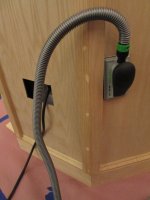
I then filled the holes with the Pacific red oak putty I still had plenty of from the previous phase, and used my newly acquired HSK sanding block + hose set to sand off the excess when dry, which I got thanks to the review posted by [member=1619]SRSemenza[/member] : http://festoolownersgroup.com/festool-tool-reviews/hsk-80-x-130-hand-sanding-block-and-hoses/

[attachthumb=15]

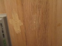
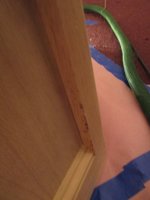
The reason I used the sanding block rather than something like the ETS 150 or the RTS 400, is that I found the block did not leave and/or create the kind of residue build-up in the oak's very open grain as I discovered it did in the previous phase of the project -- and which required a lot of elbow grease to remove -- as you can see here after using the electric sander:

[attachthumb=16]

Maybe it has something to do with the sander's vibration.  In any case, it ultimately did not matter a great deal, since the Osmo finish brings this particular filler to almost the same color as the wood.  But hey, new toy.

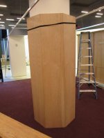
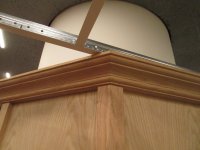
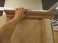
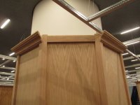
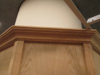
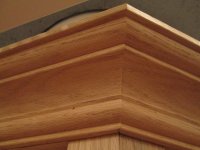
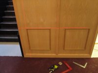
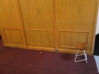
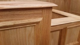
This is what they looked like after the base cap had also been put in:

[attachthumb=17]

Next up, crown moulding and finish
 

Attachments

  • IMG_5767.JPG
    IMG_5767.JPG
    441.1 KB · Views: 193
  • IMG_5778.JPG
    IMG_5778.JPG
    425.7 KB · Views: 178
  • IMG_5779.JPG
    IMG_5779.JPG
    413.2 KB · Views: 179
  • IMG_5780.JPG
    IMG_5780.JPG
    460.1 KB · Views: 175
  • IMG_5784.JPG
    IMG_5784.JPG
    424.5 KB · Views: 202
  • IMG_5785.JPG
    IMG_5785.JPG
    411.5 KB · Views: 178
  • IMG_5782.JPG
    IMG_5782.JPG
    459.8 KB · Views: 193
  • IMG_5764.JPG
    IMG_5764.JPG
    478.3 KB · Views: 170
  • IMG_5757.JPG
    IMG_5757.JPG
    349.8 KB · Views: 172
  • IMG_5760.JPG
    IMG_5760.JPG
    411 KB · Views: 173
  • IMG_5743.JPG
    IMG_5743.JPG
    413 KB · Views: 169
  • IMG_5747.JPG
    IMG_5747.JPG
    491.6 KB · Views: 191
  • IMG_5748.JPG
    IMG_5748.JPG
    447.7 KB · Views: 169
  • IMG_5749.JPG
    IMG_5749.JPG
    438.4 KB · Views: 195
  • IMG_5750.JPG
    IMG_5750.JPG
    474.7 KB · Views: 165
  • IMG_5758.JPG
    IMG_5758.JPG
    427.1 KB · Views: 219
  • IMG_5759.JPG
    IMG_5759.JPG
    375 KB · Views: 183
I was anxious about doing the crown moulding, with nothing but outside corners and an unforgiving natural finish.  I can actually count on one hand the number of crown moulding installs I've done.  Two on art installations (including the wall crown for the courtroom I did prior to the filming), and one last summer when I renovated the master bedroom in my house.  And the courtroom was the first time I had done one with a natural finish.

But in the end it turned out to be a lot easier than I anticipated, due, I think, to the fact that I had been able to be so precise with building the structure thanks to the track saw.  Having the frame for the drop ceiling already in place was not a hindrance either.

[attachthumb=9]

I first used scrap to put backing boards so the gap created by the crown resting on the battens would be closed, as I had already done on the walls, marking the position with the Incra flexible ruler, a measuring instrument for which I'm constantly finding more uses:

[attachthumb=1]

[attachthumb=2]

Measuring was the hardest part, so I simply rough cut long and then marked off and recut where the joint would be, proceeding piece by piece, using the Gary Katz method of a clamped crown stop on the Kapex and cutting it upside down:

[attachthumb=3]

[attachthumb=4]

I again used an 18 gauge nailer to secure the boards to the structure, and a 23 gauge pin nailer for the joints.  I probably overused the pin nailer, but I felt I needed the additional security.  I was worried about the last piece in particular:

[attachthumb=5]

But the last piece actually had the best joints, as I found it could be cut ever so slightly oversized and pressed in to make the joints on either side very tight.  I'm pretty happy with how the crown came out.  A few slight gaps, since the pine and thin ply structure was still fairly flexible, and so pressing on one side affected the joints on the opposite side of the polygon.  But overall the joints were pretty tight:

[attachthumb=6]

[attachthumb=7]

[attachthumb=8]

[attachthumb=10]

I then put some colonial door stop trim around the outlet cutouts, I did some spot sanding in preparation for the Osmo, getting rid of the few burn marks on the edge of the battens:

[attachthumb=11]

For the finishing, I used to great effect the Milwaukee light I had picked up -- actually purchased it when I was on my way to get a Syslite and stopped first at Home Depot, not realizing before that Milwaukee had its own version -- illuminating the "holidays" where the brush hadn't reached, as my grandfather used to called them, and the wet spots when I was wiping:

[attachthumb=12]

[attachthumb=13]

Found that a piece of scrap with a sharp edge wrapped in a cloth was good for wiping the profile edges:

[attachthumb=14]

I'm really happy with the finished product.  I now think it might have made them even better to add a small profile to the battens, or at least soften the edges a bit.  But all in all they are pretty good as is, and I'm sure are more than sufficient for an installation of this type:

[attachthumb=15]

[attachthumb=16]
 

Attachments

  • IMG_5839.JPG
    IMG_5839.JPG
    442.8 KB · Views: 169
  • IMG_5852.JPG
    IMG_5852.JPG
    399 KB · Views: 161
  • IMG_5858.JPG
    IMG_5858.JPG
    431.5 KB · Views: 204
  • IMG_5857.JPG
    IMG_5857.JPG
    436 KB · Views: 160
  • IMG_5859.JPG
    IMG_5859.JPG
    505.9 KB · Views: 183
  • IMG_5903.JPG
    IMG_5903.JPG
    464.6 KB · Views: 190
  • IMG_5908.JPG
    IMG_5908.JPG
    504.6 KB · Views: 247
  • IMG_5836.JPG
    IMG_5836.JPG
    488.2 KB · Views: 215
  • IMG_5851.JPG
    IMG_5851.JPG
    420.2 KB · Views: 176
  • IMG_5840.JPG
    IMG_5840.JPG
    407.6 KB · Views: 177
  • IMG_5841.JPG
    IMG_5841.JPG
    476.1 KB · Views: 164
  • IMG_5828.JPG
    IMG_5828.JPG
    421.2 KB · Views: 171
  • IMG_5837.JPG
    IMG_5837.JPG
    469.1 KB · Views: 199
  • IMG_5844.JPG
    IMG_5844.JPG
    432.6 KB · Views: 180
  • IMG_5838.JPG
    IMG_5838.JPG
    405 KB · Views: 183
  • IMG_5842.JPG
    IMG_5842.JPG
    442.3 KB · Views: 173
[member=167]neilc[/member] Yeah, I was thinking of rerouting the profile as a last resort as well, but only as a last resort, since the potential for error didn't seem worth given that the profile was intact everywhere else.

neilc said:
Nice recovery.  I might have tried the saw and rail to cut back the outside by 1/4" on the three outside edges and then re-route the same profile as you had.

But you did a remarkable job!

Thanks for sharing this endeavor from planning through completion.  I learned a lot about set construction!

Neil
 
Hello Edward,

You are doing some very nice work! What will happen to the fine trim work you completed when the movie is done? Just wondering...there is a lot of nice wood that you have used.

Mike
 
[member=37411]Edward A Reno III[/member]
What a huge difference in the appearance of the "scene" when you cover the pillars. [thumbs up]  Like the octagon theme, it works well with the squareness of the rest of the courtroom items. Square pillars would have been overwhelming considering the scale of the rest of the items.

In reply #70, when you fasten 4 of the panels to each other, did you use any clamps or did you just glue them and then shoot brads into the panels to hold them?

Like the self portrait in reply #71. [big grin]
 
[member=44099]Cheese[/member]  on the pillars, I was thinking that I would have to pin it for the assembly, but they actually fit quite nicely with the 5mm dominos, so I didn't even have to.  I did use the widest mortise setting on the machine, which definitely helped with the fit. But in the end, straps were all th hat was required. Using the parallel guides was probably key for this, since it assured uniform size, and so no twisting or bending to close gaps.

Cheese said:
[member=37411]Edward A Reno III[/member]
What a huge difference in the appearance of the "scene" when you cover the pillars. [thumbs up]  Like the octagon theme, it works well with the squareness of the rest of the courtroom items. Square pillars would have been overwhelming considering the scale of the rest of the items.

In reply #70, when you fasten 4 of the panels to each other, did you use any clamps or did you just glue them and then shoot brads into the panels to hold them?

Like the self portrait in reply #71. [big grin]
 
[member=3741]limestonemike[/member] yeah, good question. It's possible  that the bench setup may be sold or reprised for another exhibit, but the larger room will have served it's purpose when the exhibition  closes. Best case is that the gallery and/or artists will donate it to one of the cheap or open source building materials places in NYC like Build It Green. Worst, and more probable case is that several thousand dollars worth of oak will go in the trash.

limestonemike said:
Hello Edward,

You are doing some very nice work! What will happen to the fine trim work you completed when the movie is done? Just wondering...there is a lot of nice wood that you have used.

Mike
 
I'm on vacation now, but since I'm up before everyone else, and it's still too early to fire up the chainsaw and continuing the forestry work I'm doing up here, thought I'd add a small build post this early morning to fill in some gaps.

As I reported some time back, the last few days of the build at the space in Queens was incredibly hectic, and a lot of different hands came on deck to do the final touches, particularly on the wall paneling and finishing.  One of the things that slipped through the cracks was proper leveling of the moulding squares on the panels.  The floor of the space was atrocious, and although the guys who erected the flats had done a good job compensating for the unevenness, they couldn't get it perfectly.  So when I set up my Bosch laser and spec'ed the job for the people who were going to be doing it, there were some spots in the room (which was 40x26) where the self-leveling laser line was off by several inches.  I seem to remember making some comment about how we'd address the problem when we got to those sections, but in our haste we never got around to it.  Incidentally, this is a case where the self-leveling function may create more problems than it solves.  Had we used another method I've employed in the past -- a piece of scrap set on the baseboard to set the bottom piece of the moulding square so that it's a consistent distance on each one of the panels -- this would have avoided all these difficulties.  But like I said, we were in a mad dash to the finish.

So when the installation was re-erected over at the art gallery, it was immediately obvious that there were some leveling issues.  I had noticed the issue even before I pulled out the laser, but with the laser you could really see how bad it was:

[attachthumb=1]

In the previous space this section had been in the far end where the camera trolley had started, and wasn't even in the film as far as I can tell, but in the new space it was right at the base of the staircase where people will be entering, and so it constituted a problem.

I ignored it for a couple of days while I went about applying some other finishing touches, like building the extra wall that was going on the other side of the staircase, which I wanted to do first in any case to establish the reference mark that I would reset the problem moulding squares to:

[attachthumb=2]

My main worries were what I would find when I took off the moulding -- could the adhesive be cleaned up, and would the raw wood under the moulding where oil had not reached be brought to the same color, or would there be a kind of shadow effect where people could see where the moulding had previously been attached?  Even if it could be cleaned, would the process perhaps result in burning the veneer, something that had occurred on several of the panels even when using the ETS 150/3 + soft pad + interface pad.

Well, it turns out that (thank God), that the applicator had just used nails and no adhesive -- a good lesson to keep on file for these sorts of projects, don't use adhesive if you don't have to so stuff can be readjusted later.  Underneath the moulding, however, there was some crusty build up from the Osmo:

[attachthumb=3]

Now, the reason I had gone with Osmo, other than its looks and durability, was because it was relatively idiot-proof.  I don't have a lot of experience with finishing outside of the work I do for myself, and on the previous installations we had always used this painter to finish my woodworking contributions, so this really was the first time I was tasked with executing the finish on an installation -- thus I wanted to go with something that I would have to actively work at to screw up.

But I now see another reason why Osmo is the bomb, which is the ease with which you can clean it off and redo it.  Armed with the ETS 150, I managed to pull off a fix that left me feeling like a professional finisher.  I used the green vlies pad to clean around the area where the moulding had been:         

[attachthumb=4]

The green pad was perfect for the job -- abrasive enough to get the build up and blend the border between the finished and non-finished areas, but not so harsh that it would actually dig in to the veneer:

[attachthumb=5]

And here's the spot where that previously pictured crusty build-up had been:

[attachthumb=6]

I reattached the squares, now in a proper line:

[attachthumb=7]

And then reapplied some Osmo.  Forgot to take a straight on picture of the corrected wall, but you'll have to believe me when I say that you can't it was readjusted, and be content with this indirect shot:

[attachthumb=8]

So thanks Osmo, and thanks too, [member=11196]Peter Parfitt[/member] for the helpful how to videos on working with it.
 

Attachments

  • IMG_5912.JPG
    IMG_5912.JPG
    466.8 KB · Views: 156
  • IMG_5812.JPG
    IMG_5812.JPG
    414.7 KB · Views: 154
  • IMG_5810.JPG
    IMG_5810.JPG
    437.5 KB · Views: 139
  • IMG_5811.JPG
    IMG_5811.JPG
    434.3 KB · Views: 144
  • IMG_5805.JPG
    IMG_5805.JPG
    423.2 KB · Views: 153
  • IMG_5807.JPG
    IMG_5807.JPG
    397.5 KB · Views: 146
  • IMG_5803.JPG
    IMG_5803.JPG
    403.7 KB · Views: 151
  • IMG_5804.JPG
    IMG_5804.JPG
    424.1 KB · Views: 183
When I get back from vacation I will probably add a few more finishing touches to the courtroom, like the ceiling, but for now it's essentially finished.  So here are a few pictures of the completed work:

[attachthumb=1]

[attachthumb=2]

[attachthumb=3]

[attachthumb=4]

[attachthumb=5]

[attachthumb=6]

[attachthumb=7]

[attachthumb=9]

[attachthumb=8]

[attachthumb=10]

And here's the kit I used for this second phase of the build, all ready to migrate back to home base:

[attachthumb=11]

I'll post more details about the opening, which will be in the second week of September, when I get them.


Attachments

  • 20150817_143707.jpg
    20150817_143707.jpg
    3.1 MB · Views: 181
  • 20150817_143658.jpg
    20150817_143658.jpg
    2.7 MB · Views: 153
  • 20150817_143650.jpg
    20150817_143650.jpg
    3 MB · Views: 151
  • 20150817_143551.jpg
    20150817_143551.jpg
    3.6 MB · Views: 145
  • 20150817_143433.jpg
    20150817_143433.jpg
    1.4 MB · Views: 158
  • 20150817_143340[1].jpg
    20150817_143340[1].jpg
    2.9 MB · Views: 183
  • 20150817_143332[1].jpg
    20150817_143332[1].jpg
    2.9 MB · Views: 158
  • 20150817_143229[1].jpg
    20150817_143229[1].jpg
    3.4 MB · Views: 172
  • 20150817_143212[1].jpg
    20150817_143212[1].jpg
    2.5 MB · Views: 174
  • 20150817_143105[1].jpg
    20150817_143105[1].jpg
    2.6 MB · Views: 190
  • IMG_5916.JPG
    IMG_5916.JPG
    447.5 KB · Views: 221
Many thanks Edward for taking the time to mention my very small part in your wonderful story.

Cheers.

Peter
 
For anyone in NYC or going to be there in the next few months, the show is opening on Sept. 12 and will be up through early December at Red Bull Studios, located at 220 W. 18th street, New York, NY 10011. More info here:

http://www.redbullstudiosnewyork.com/exhibition/scenario-in-the-shade/

As I've said before, there's a lot more to it than just the courtroom. The whole gallery space, which is substantial, been transformed into a series of immersion sets/environment that can be entered and occupied.

As I will probably be adding a few more finishing  touches, like the ceiling and the staircase  entrance to the room, I'll likely be posting a few more build details  in the coming week.
 
Back
Top