Hinge boring question of 1010

TheTrooper

Member
Joined
Mar 19, 2015
Messages
247
I'm going to use my OF1010 for the first time to bore 35mm hinge holes. Can anyone suggest what speed to use? I normally do this by hand. I'm guessing 6 answer slow steady plunge, I am using the LS32 system
 
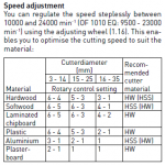
For a 25-50mm bit, generally you want a speed of about 18,000 RPM, which is somewhere between 4 and 5 on the OF 1010. Obviously material type can also affect speed selection; I've assumed this is into softwood or particle board. The following guide from the OF 1010 manual may also help.

[attachimg=1]
 

Attachments

  • ScreenShot157.png
    ScreenShot157.png
    25 KB · Views: 722
I wind the machine right down to 1 for cutting out hinge holes, you will cook the bit at a faster speed.
I think it does suggest that in the LR32 manual somewhere.
 
Trans former said:
I think it does suggest that in the LR32 manual somewhere.

There is nothing about bit speed in the LR-32 manual, but I do note that [member=1146]Brice Burrell[/member] suggests using speed 1 in his video for Festool and in his guide to the LR-32 system; YMMV depending on your technique and the material.

Seems [member=8251]ccarrolladams[/member] also suggest dialling the speed right down at http://festoolownersgroup.com/festool-tools-accessories/through-vs-stopped-5mm-bit/msg400368/#msg400368

[EDIT - added information from another post]
 
Is there an advantage to not using a drill?

Or why wouldn't one plunge with a smaller bit and run around in a circle using a template?
 
Holmz said:
Is there an advantage to not using a drill?

Or why wouldn't one plunge with a smaller bit and run around in a circle using a template?

Please understand that the Festool hinge boring bits are designed specifically for that purpose, so they are not the same as drill bits. They are also designed to stand up to the minimum speed of the OF1010, which is many times faster than drills.

In metal fabrication back in the old days there were precise machines known as jig borers used to make ultra accurate round holes which used the approach of moving the work piece under a stationary end mill cutter smaller than the desired hole in such a way the end mill created an accurate hole. For making fairly small through holes you would precisely drill a slightly under-sized hole. The next step would be to change from a drill bit to a reamer ground to create a round hole of exactly the desired diameter. For any number of reasons using reamers never worked out in the real world of woodworking. Trust me, 60 some years ago people coming to woodworking after gaining experience doing precision metalworking actually failed at attempts to make better quality holes in wood by using reamers. We made spectacular tear-out.

With the introduction of NC machining, that sort of control was added to refined end milling machines. One of the first popular uses was for production hole boring. The table of the NC end milling machine was caused to move to create a perfect round hole using a smaller end mill cutter.

Years later CNC came along, replacing the punched tape and cards of NC with computer software. In many applications the table holding the work remained stationary and the milling machine spindle is moved on a gantry under computer control. That increased production speed and made accuracy easier to achieve.

I got my start in metal working just before the NC era. I am not aware anyone seriously considered using NC in woodworking.

After the cost of CNC milling machines was reduced, for woodworking CNC routers were created. At first the cost of CNC routers was very high compared to other woodworking machines and yet far lower than for traditional metalworking CNC machines. Many current CNC routers can be used with softer metals and plastics, frequently using different spindles running at lower RPM.

With modern CNC routers a common approach for creating accurate round holes is to move the router bit in a circle, as you suggested using software as a virtual template. Festool has never confided in me how they produce the MFT-style work tables with precise 20mm dia holes on 96mm centers.

My cabinet shop makes our own very large MFT-style work tables using one of our CNC Routers. We use the software approach of using an under-size bit moved in a circle so that software creates the all-important 20mm round hole on exactly 96mm centers.

Again in the real world of making cabinet doors customers can afford, the makers of cup hinges accept that the holes bored in solid wood or sheet material will not be perfectly round, but when made with correctly designed cutters those shallow holes are accurate enough for the purpose. Notice that the hinges have a 'bezzle' which hides the hole holding the cup hinges from the client's view. In making cabinets it is the positioning of the hinge hole that is more important than the exact size of the hole. The grain of the wood frustrates creating perfect holes with a single bit, so the hinge system was created to work well in the real world.
 
This table would suggest that the dial should be set to 1 for a 35mm bore bit and 5-6 for the 5mm bit.

GarryMartin said:
For a 25-50mm bit, generally you want a speed of about 18,000 RPM, which is somewhere between 4 and 5 on the OF 1010. Obviously material type can also affect speed selection; I've assumed this is into softwood or particle board. The following guide from the OF 1010 manual may also help.

[attachimg=1]
 
CCaroll and I probably started with NC at about the same time. My baptism came before the advent of 'circular interpolation' which accomplishes a milled bore in on line of code. The original process was a series of linear commands in very small increments stitched together to make your way around the arc. Think of tacking a sailboat around Cape Horn. We ran a job with an arc covering about 45 degrees with about a five inch radius. The tape was about 150 yards long. We could run the job, check dimensions unload and load another part before the tape rewound. The thought of using CNC economically on wood products was on no one's radar at that time. There were many skeptics even in metalworking industries. Not me. The first time I saw a CNC lathe cut a thread I was in love. Roughing work on an engine lathe and dodging hot chips had worn pretty thin for me.
 
Finally drilled the 24 hinge holes today on setting 1. Thanks for all the help guys.
However I did come across another issue. I zeroed out the router and then set the depth to 10mm for my holes. The 1st one was perfect, then the next 2 was at 14mm.  I figured, okay it's the 2nd time using the router so maybe it's setting. I zeroed the router again. The 1st hole was at 10mm and the  next 2 was between 13-15mm. Am I doing something wrong?
 
TheTrooper said:
Finally drilled the 24 hinge holes today on setting 1. Thanks for all the help guys.
However I did come across another issue. I zeroed out the router and then set the depth to 10mm for my holes. The 1st one was perfect, then the next 2 was at 14mm.  I figured, okay it's the 2nd time using the router so maybe it's setting. I zeroed the router again. The 1st hole was at 10mm and the  next 2 was between 13-15mm. Am I doing something wrong?

Run the router and watch the depth stop adjusting dial. It is most probably turning causing the plunges to change depth. There are parts that need to be changed in the mechanism to correct this. Forgot what they are but I need to find it again, mine has this issue.

Tom
 
I own them both. For the LR 32 I prefer the 1010, lighter plunge easier. 1400 depth rod dial has a better 0.1 mm detent.

I have "solved" the problem with mine by making sure I thigh the dial. This takes away the adjustment but....

Tom
 
Back
Top