Installing LED strips and other LED issues

Cheese

Member
Joined
Jan 16, 2015
Messages
12,503
A sister thread on LED lighting:http://festoolownersgroup.com/festo...led-lights-using-the-mfs/msg577072/#msg577072

I'll try not to get too nerdy on this subject but that will be tough to achieve.  [smile]

The first part of this post will be installing the LED strips in the stretchers I made for some cabinets.

The next posts will just be an assemblage of various information I've acquired in the 15+ years of working with LEDs. I'm by no means an expert on the subject, but having worked with them for such a long time I've stumbled upon some interesting items.

As the saying goes, "Even a blind squirrel finds a nut once in a while".

Feel free to chime in.

Here's just a little bit of background information to put the ensuing conversation in proper context.

The bane of all LEDs is heat. The magic temperatures for cooking are 40ºF and 140ºF.  For LEDs the magic temperature is under 150ºC. The junction temperature of the LED must be kept to a MAX of 150ºC, preferably a lot less. As an example, If an LED has a rated 60,000 hour life at 125ºC its life is reduced to only 10,000 hours at 150ºC and anything in excess of that just creates a rapid downward spiral.

Here's a cross section of an LED. The junction is the pink area and the thick green area is whatever substrate the LED is mounted on. It may be a circuit board or it may be tape. There can be quite a distance between the LED junctions and the heatsink. So if the heatsink is measuring 150ºC, the junctions will likely be over 180ºC. Keep it cool, the cooler the better.

[attachimg=1]

So with that out of the way let's install the LEDs in the stretchers. I've learned/prefer to mount all the LEDs on some type of heat sink. I know some manufacturers say to just peel off the double stick tape liner and stick the tape to any surface you want. That may be ok on metal surfaces but on wood surfaces you're adhering the LEDs to an insulator. More on this later with some interesting photos to share.

Also, if you have a problem with the LEDs down the road it's simple to remove the LEDs with a few screws rather than unpeeling them and then having to remove the adhesive that's left behind.

For this project I used Lighting Ever LEDs on a roll. They're 2835 LEDs and burn at 4100K so they're very efficient. They produce a lot of light with little current draw. The 2 sided tape used is 3M VHB so they will stick to a lot of different surfaces.

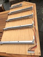
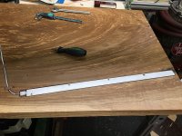
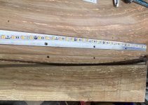
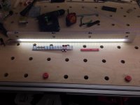
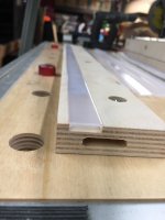
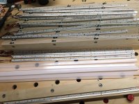
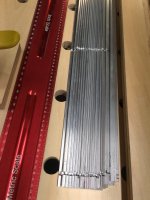
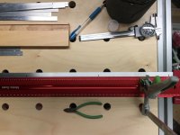
I used 1/2" wide by 1/16" thick aluminum flats for the heatsink. Here's a photo of the aluminum being marked for the hole punching stage.

[attachimg=2]

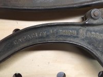
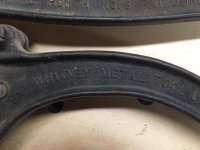
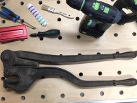
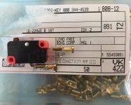
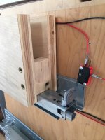
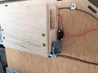
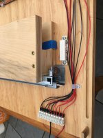
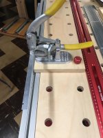
Here's a Roper Whitney hand punch in a bench mount that's used to punch the 4 attachment holes.

[attachimg=3]

[attachimg=4]

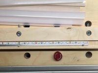
A couple of good wipes with IPA and the aluminum is ready for the LEDs.

[attachimg=5]

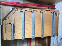
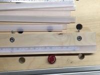
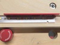
I used a 2mm gauge block to evenly space the heatsink from the channel. I placed the gauge block behind every screw hole and then drove in the screws. The gauge block prevented the heatsink from moving as the screws are driven home.

[attachimg=6]

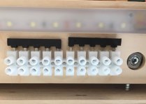
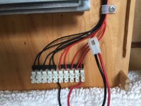
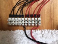
The LED assemblies are held in with 4 each #4 screws.

[attachimg=7]

The Diode LED covers are snapped into place.

[attachimg=8]

[attachimg=9]
 
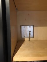
Here they are fired up. You can see they provide more than enough light for a drawer.  [big grin]  I turned one on and let it burn for 48 hours continuously. The room temperature was 67ºF, the heatsink temperature after 48 hours was 74ºF.  [cool]

[attachimg=10]

[attachimg=11]
 

Attachments

  • 001.png
    001.png
    62.8 KB · Views: 2,254
  • 6854.JPG
    6854.JPG
    239.8 KB · Views: 2,077
  • 6844.JPG
    6844.JPG
    257.5 KB · Views: 2,148
  • 6828.JPG
    6828.JPG
    712.1 KB · Views: 2,211
  • 6827.JPG
    6827.JPG
    227.8 KB · Views: 2,125
  • 6826.JPG
    6826.JPG
    231.7 KB · Views: 2,151
  • 6825a.JPG
    6825a.JPG
    744.8 KB · Views: 2,166
  • 6824.JPG
    6824.JPG
    436.4 KB · Views: 2,175
  • 5740.jpg
    5740.jpg
    929.9 KB · Views: 2,110
  • 5741.JPG
    5741.JPG
    644.7 KB · Views: 2,160
  • 5738.jpg
    5738.jpg
    749.8 KB · Views: 2,202
Time for questions? 
What is the tie bar?  (the heat sink or the cross member you're attaching the heat sink to)
Can you drill through the tape or does it have sufficient wiring embedded that it should be left intact?
When do we get to the part about the switches?  (waits impatiently)  [smile]

Thanks for writing this up!
 
Very nice and good pics as usual.

The Roper/Whitney is nice but I was hoping for at least a 25 ton ironworker.  [wink]

Ron
 
Thanks for going nerdy on the led strips.
I didn’t do any research so I’m just now learning about the need for heat sinks.
 
Me too. Im planning on using led strips to illuminate above a "broken glass" ceiling in my ensuite. Ive had led strips explode and catch fire in the past which worried me, they were covered in a kind of clear plastic sheath which i guess insulated them. I guess i need to find some aluminum, we only have aluminium in the uk, will that do the job?  [tongue]
 
RKA said:
Time for questions? 
What is the tie bar?  (the heat sink or the cross member you're attaching the heat sink to)
Can you drill through the tape or does it have sufficient wiring embedded that it should be left intact?
When do we get to the part about the switches?  (waits impatiently)  [smile]

Raj, The stretcher (tie-bar) is the piece of 18 mm thick BB that ties together both vertical sides of the cabinet and it also houses the LED lighting.

Best not to drill through the tape as it is the "circuit board" that provides juice to the LEDs. Keep it intact.  [smile]

By popular demand, the microswitch section will be the next entry (even though the author waits impatiently to be nerdy on other aspects of LEDs).
 
[member=3192]rvieceli[/member]

An ironworker...I wish that were so Ron [sad]

I do have what may be a poor cousin to the Ironworker....but it was a little large to put into a bench mount.  [eek]

[attachimg=1]

[attachimg=2]

The 1/4" hole in 1/4" thick steel is still pretty impressive even in todays terms.

[attachimg=3]


Attachments

  • 6865.jpg
    6865.jpg
    298.1 KB · Views: 1,964
  • 6864.jpg
    6864.jpg
    345.9 KB · Views: 2,026
  • 6863.jpg
    6863.jpg
    287.3 KB · Views: 1,972
Michael Kellough said:
Thanks for going nerdy on the led strips.
I didn’t do any research so I’m just now learning about the need for heat sinks.

Cooling is your friend Michael...I can't repeat this enough. I've spent 30 years of my life immersed in the semiconductor field and LEDs  are nothing more than another item grown on a silicon chip. There are 2 things that will take them out, too much current and too much heat.
 
[member=44099]Cheese[/member] my son just started a new job at a fabrication place a couple towns over. They have a 160 ton press with all kinds of spiffy high tech controls on it.

Ron
 
Russty said:
Me too. Im planning on using led strips to illuminate above a "broken glass" ceiling in my ensuite. Ive had led strips explode and catch fire in the past which worried me, they were covered in a kind of clear plastic sheath which i guess insulated them. I guess i need to find some aluminum, we only have aluminium in the uk, will that do the job?  [tongue]
  I thought it was AL-U-MIN-UM.... at least it sounds that way when I hear the word coming out of a Brit's mouth..... [wink]
 
Russty said:
I've had led strips explode and catch fire in the past which worried me, they were covered in a kind of clear plastic sheath which i guess insulated them. I guess i need to find some aluminum, we only have aluminium in the uk, will that do the job?  [tongue]

I think the LEDs you're referring to were of the waterproof variety. They're covered in a clear, half-round vinyl cover. I'll have more to say on those later.

Well as leaky points out AL-U-MIN-IUM is actually the preferred material for heatsinks as it has better thermal conductivity. But because it's next to impossible to find in the states, we have to settle for the poor cousin of it...plain old aluminum.  [poke]
 
rvieceli said:
[member=44099]Cheese[/member] my son just started a new job at a fabrication place a couple towns over. They have a 160 ton press with all kinds of spiffy high tech controls on it.

Ron, it always amazes me how much capitol needs to be invested in starting a metal fab shop. If you want to be a carpenter spending $10,000 gets you going in the right direction. For metal fab, $10,000 gets you a TIG, a welding table and maybe a decent drill press.  [eek]

That's the reason I usually shop the used market for many metal fab items. Metal fab shops open and metal fab shops close every day. There are a lot of items that were purchased and never used before the doors were shuttered.
 
When I started this project I decided the easiest/slickest method to actuate the LED lighting was using an encapsulated reed switch actuated by a rare earth magnet counterbored into the rear of the drawer. The ONE sample I rigged up worked perfectly. Here's a "mini drawer" I fabricated to determine the proper placement of each reed switch/magnet pairing. That's a magnet underneath the blue tape.

[attachimg=1]

So, flying high from my success, I purchased $120 of reed switches and  magnets. I then installed 5 of them in a cabinet and used the "mini drawer" to functionally test the setup.

[attachimg=2]

Well ONE sample does not a design of experiments make.  [crying]  Of the 5 reed switches I installed, 2 always worked properly but 3 of them would actuate but would never shut off unless you hit them with a screwdriver handle. I believe it was the high level of in-rush current drawn by the LEDs that was "welding" the reed switch conductors together. Then when you rapped them with the screwdriver, you'd break the weld and they would spring apart. 

I'm sure there's an electronic work-around for this issue but that's several levels above my pay grade.

So back to old tech microswitches. They're cheap and reliable and have a typical life span of 1 million cycles. I purchased these from Amazon for $8 for a pack of 5. The reed switches were $4 each. This option really does work well and it's something I'll never have to revisit in my lifetime.

[attachimg=3]

In this view you can see the "mini drawer" pushed forward to expose the small hole needed for the self-closing Blumotion slides.

[attachimg=4]

Here's a shot of the XURUI microswitch along with the proper size quick connect ends. While 1/4" wide is common for most electrical items, microswitches use 3/16" wide connectors. These are from Digi-Key. While I would have preferred purchasing Honeywell microswitches because they're only about 50 cents more and they're local, Mouser was out of stock at the time. Omron is another good brand to look at.

[attachimg=5]

Here's an overall shot of one side of the cabinet.

[attachimg=6]

Photos of the European terminal strip, the Molex wire connection and the Altec terminal jumpers.

[attachimg=7]

[attachimg=8]

[attachimg=9]
 

Attachments

  • 6860.jpg
    6860.jpg
    138.7 KB · Views: 1,858
  • 6858.JPG
    6858.JPG
    990.4 KB · Views: 1,997
  • 6857.JPG
    6857.JPG
    921.3 KB · Views: 2,157
  • 6663.JPG
    6663.JPG
    1 MB · Views: 1,913
  • 6859.jpg
    6859.jpg
    235.2 KB · Views: 1,912
  • 6856.JPG
    6856.JPG
    876.7 KB · Views: 1,882
  • 6855.JPG
    6855.JPG
    317.2 KB · Views: 1,890
  • 4358.jpg
    4358.jpg
    785.2 KB · Views: 1,941
  • 4360.jpg
    4360.jpg
    731.2 KB · Views: 1,914
neilc said:
Nice work!  Thanks for the tutorial!

Thanks Neil...this thread is nowhere from being finished. I plan to add to it a little everyday as that’s how I learned about LEDs...a little everyday.  [smile]

The downside is that it is robbing time for me to learn Fushion 360 and to fire up that Shaper.  [crying] [crying]
 
Combine those interests.

I make these LED-lit nightlights for baby gifts.  All cut with the Shaper.  I've done them with painted as well as natural bases. 

The LED kits I buy from Amazon as well as the cast acrylic sheets. 

Lights are multi-colored which add entertainment value as the babies grow up and want to learn their colors.  And wireless remote control.

[attachimg=1]
 

Attachments

  • IMG_0835.jpg
    IMG_0835.jpg
    279.6 KB · Views: 1,906
So one of the more obscure terminologies with using LEDs is that they need a "Driver" to be functional. In layman's terms a "driver" is nothing more than a power supply. It's usually a 12 volt or 24 volt solid state transformer. For the most part it is encapsulated in a plastic housing which will give it a certain amount of water protection. They'll typically have an IP (Ingress Protection) rating from IP 62 to IP 68. An IP 68 rating is defined by the official words "Protected from long term immersion up to a specified pressure and totally protected from dust ingress."

They are certainly not your old school ventilated power supply. They are inexpensive and bomb proof. I've had 2 each Triad 40 watt power supplies powering the outside garden lights for the last 12 years. That includes 20+ fence lights, 30+ garden luminaries and 5 spot lights.
The Triad power supplies are controlled by 2 photo sensors. One for the front yard lighting and one for the back yard. They turn the LEDs on at dusk and off at dawn. The total cost per month is around $1.50.
And the outside scene at nite is brilliant. It's a wonderful world to walk into at night and it's also a wonderful deterrent to when someone thinks that what you own is what they need to own. [big grin]

[attachimg=1]

[attachimg=2]

[attachimg=3]

I prefer using Meanwell drivers for interior LED lighting. They are also recommended by Diode LED for driving their LEDs. They are inexpensive, small, well sealed and reliable. They come in a plethora of wattages. The fewer watts, the smaller the package.
https://led.meanwell.com

When I redid the one side of the kitchen 5 years ago I knew I wanted some under counter task lighting so I added an electrical box in the wall. I placed a small, $10 Mean Well 12 watt driver in the electrical box. The 2 leads exiting the enclosure drive a Diode LED light bar under the cabinet and a strip of Diode LED Ultra Blaze on a heat sink placed in the countertop.

[attachimg=4]

[attachimg=5]

The heat sink is 1" x 1/8" aluminum flat. It's attached to the countertop using traditional machine screws so everything is flush.

[attachimg=6]

[attachimg=7]
 

Attachments

  • 5248.JPG
    5248.JPG
    788 KB · Views: 1,769
  • 5295.JPG
    5295.JPG
    692.9 KB · Views: 1,773
  • 6868.JPG
    6868.JPG
    722.7 KB · Views: 1,767
  • 301_5662.JPG
    301_5662.JPG
    596 KB · Views: 1,837
  • 6815.JPG
    6815.JPG
    418.7 KB · Views: 1,768
  • 6813.JPG
    6813.JPG
    395.6 KB · Views: 1,776
  • 5244.jpg
    5244.jpg
    921.8 KB · Views: 1,694
neilc said:
Combine those interests.

I make these LED-lit nightlights for baby gifts.  All cut with the Shaper.  I've done them with painted as well as natural bases. 

The LED kits I buy from Amazon as well as the cast acrylic sheets. 

Lights are multi-colored which add entertainment value as the babies grow up and want to learn their colors.  And wireless remote control.

Nice stuff Neil...you continue to surprise and delight. I just wish I could wrap my head around Fushion 360...I'd be a new person.  [smile]
 
The electronic equivalent of the reed switch would be a hall effect sensor, coupled to a relay (probably the simplest and could handle a variety of current loads. Mosfets would be an alternative to the relay.)

The circuitry is quite simple, but it would be a bit more of a fiddle than the microswitches.

The other alternative would be to use the reed switch to trigger a relay, and then have the relay handle the higher current to power the LEDS. Again, a few more components, but you wouldn't have the reeds singeing themselves together.
 
Back
Top