It took me 5 versions to get it right

Crazyraceguy

Member
Joined
Oct 16, 2015
Messages
4,887
I should have taken a picture of the bottom of this pull. The shape is very complicated and rather difficult to measure. I got it pretty close the first time, wrestling with the Studio app on my phone. It is far more difficult than doing it with my laptop. So, I decided to leave it until the next day and re-do it at home.
It was still off a little. I had the pocket, below the Mickey Mouse ears, a little too wide. That doesn't leave enough material for the screws, so I had to shrink that back. (with the phone again)
It ended up being an almost perfect fit, which in retrospect is probably not necessary anyway [unsure]
No one will ever see it, but if they do.....they'll surely be impressed [big grin] and wonder how it was done.
In reality, I suppose a simple rectangle that left space for the screws would work. Where's the fun in that though?
 

Attachments

  • Ardent fireplace panel.jpg
    Ardent fireplace panel.jpg
    259.2 KB · Views: 339
  • Ardent fireplace panel pull.jpg
    Ardent fireplace panel pull.jpg
    260.3 KB · Views: 328
Kudos for trying. I'd probably give up after the second failure. I wonder if doing it by hand would be less work.

Btw, I'd try to align the screws to the same orientation (like clocking hinge screws).
 
I think it looks pretty good. And I agree, trying to work on the phone is difficult.

ChuckS said:
Btw, I'd try to align the screws to the same orientation (like clocking hinge screws).

Do you also orient your switch cover screws in the same direction?

(I do)  [wink]
 
That’s pretty spooky [eek] I only ever installed one of those once - on a large hinged pull-up floor panel which revealed a pair of gas struts, and an access stairway down to a wine cellar. I used exactly the same method as you.

It’s spooky because I did that job 12 years ago to the day - and I’m going back there today to quote another job.
 
Just an idea how to build a CAD model of the back of the draw pull....
Some CAD software allows you to trace a photograph (I know FreeCAD can do it, but I've never tried).
You could take a photo of the back of the draw pull and trace around it in the CAD software.
You would need to make sure the photo was very close to being parallel with the surface to avoid the X-Y plane being out of scale.

Just a thought

Regards
Bob

 
4nthony said:
I think it looks pretty good. And I agree, trying to work on the phone is difficult.

ChuckS said:
Btw, I'd try to align the screws to the same orientation (like clocking hinge screws).

Do you also orient your switch cover screws in the same direction?

(I do)  [wink]
Ha! I never paid attention to them until now. This is what I found out:

Done by the builder:

[attachimg=1]

Done by me after I removed and replaced the cover to fix a switch problem recently:

[attachimg=2]

Shall we say "woodworking habit dies hard"?
 

Attachments

  • screws1.JPG
    screws1.JPG
    12.6 KB · Views: 499
  • screws 2.JPG
    screws 2.JPG
    7.5 KB · Views: 491
Fun fact = old-school joiners/trim carpenters always aligned their screw head slots vertically, so that when someone decided to paint over them in the future (as they inevitably would) - the paint would run down the vertical channel instead of filling up the slot. I’ve taken off 200-year-old door hinges whose slots were still almost clear, despite numerous layers of historical paint.
 
Crazyraceguy said:
I should have taken a picture of the bottom of this pull. The shape is very complicated and rather difficult to measure. I got it pretty close the first time, wrestling with the Studio app on my phone.

I wonder if Shaper Trace would have worked better?
 
I do line them up vertically with slotted screws, just don't bother with Phillips.

It was very close, the first time. I just had the little loops too high. After moving them, I realized that there wasn't enough material around the screws. Driving them in would have definitely crumbled, even predrilled. It took a few tries to get that right. The software (actually web-app) works differently on the phone and I don't like it at all.
I thought about taking the pull itself up into the office and just running on the copier. At that point, I could trace around it, since I did get a pack of tracing paper a few months ago. Then the Trace frame could have made it nearly perfect.
I was just hoping I could get it through the Studio app, rather than "starting over". It may have been the same either way  [unsure]

woodbutcherbower said:
That’s pretty spooky [eek] I only ever installed one of those once - on a large hinged pull-up floor panel which revealed a pair of gas struts, and an access stairway down to a wine cellar. I used exactly the same method as you.

It’s spooky because I did that job 12 years ago to the day - and I’m going back there today to quote another job.
That's pretty wild. It's funny enough to go back to the same job on the exact day too.
I have done several different shapes over the years, but always by making a template out of 1/4" MDF.
I wouldn't have tried to get that close though. A simple deeper rectangle inside of the screw pattern would have worked.
This is clearly a case of "when you're a hammer, everything looks like a nail" I only did it this way "because I could"
It did work better, doing it this way, because the pull fit, straight off of the tool. Getting that shallow relief cut with that small of a bit (for the corners) would have been quite a pain, taking multiple templates, because clearing that out with a tiny bit would be very slow (tedious)
Once the program was sorted, it only takes about 3 minutes to cut this out, including a bit change.
It would have more beneficial, if there were more of them to do too.
This is part of that big job, so it might pop up again.

 
I've seen YT videos about software that uses your phone as a 3D scanner to produce a file that could be transformed into something that could be fed into a Shaper Origin...
 
Sanity check for [member=57948]ChuckS[/member] and [member=75283]4nthony[/member] ...

I'm wiring in a couple of 3-way switches in the garage so I pulled out my reference.

[attachimg=1]

And then while looking for the 3-way wiring diagram I stumbled upon page 50... [big grin]

[attachimg=2]
 

Attachments

  • 15218.jpeg
    15218.jpeg
    1.1 MB · Views: 322
  • 15217.jpg
    15217.jpg
    1 MB · Views: 316
On standard on/off switches, my upper slotted screws are vertical, and the lower is horizontal (too much time in Computer Science)

On three-ways, it depends, but often they'll both be vertical.

On a pair of switches, I usually put them all at 45 degrees to make a large "x"
\ /
/ \

On a 3- or- more-gang box , the middle switch(es) are horizontal top and bottom, the outer switches have their slots at 45 degrees to make a clipped-corner box pattern.
/--\
\--/

I get bored easily...
 
Too bad the world isn't all torx. Of course, they now have snap-on faceplates with no exposed screwheads.

 
I’d placed the slots like this:

Top screws at 2 o’clock
Bottom screws at 10 or 12 o’Clock

Assuming that flicking the switch up is on and down is off?
- If not, the opposite  [big grin] [big grin]
 
FestitaMakool said:
Assuming that flicking the switch up is on and down is off?
- If not, the opposite  [big grin] [big grin]

From what I have seen, that is pretty much the standard, but I don't know if it's code or not? I would think it probably is, but 3-way switches kind of ruin that, so maybe not?
 
I wrote this up in 2011:https://www.inthewoodshop.com/Furniture/FittingHandles.html

Fitting Handles to the Military Chests


I spent a long time choosing the handles for these chests right at the start of the project, and then had to hunt around to find a decent quality in the size I wanted. The small size did restrict the choice – I just did not feel that anything larger would look right.

The handles all seem to be made in India these days, where they are cast in brass from the same molds. Finish seems to be a belt sander and then a polishing disk, with lacquer added at the end. The problem is that the handles all end up with dubbed edges and rounded faces. Every website around the world either uses the same publicity photograph, or they all end up looking the same.

I managed to find a supplier in Perth who had stocks from two manufacturers. One set of handles was dubbed and rounded over, and the other was dubbed but flat. I went for the dubbed but flat version.

After all this I was still unhappy with the handles. The edges were wavy (which would not look neat in a recess), and the shiny brass looked … well, too shiny. The inside edges of the pull were sharp enough to cut a finger.

So the first step was to fettle all the handles. This involved removing the protective lacquer – I plan to let the brass age naturally – flattening the top and smoothing the pull with 800 grit wet-and-dry followed by #0000 steel wool, and finally squaring the ends with a file.

Fettled and Original …

FittingHandles_html_5c6966d3.jpg


FittingHandles_html_3fa35db.jpg


Templates

A template is needed to position the handles on the drawer fronts, and another is needed to outline the recess for each handle.

The template for positioning was made with a sheet of copy paper …

FittingHandles_html_23dbe2e0.jpg


The position was traced in with a pencil.

… while a template for the recess was shaped in MDF to reflect the shape at the rear of the handle …

FittingHandles_html_mcc44ec5.jpg


The combination of the two above produced this …

FittingHandles_html_m43d4eed3.jpg


Handle morticing

The inner recess was excavated freehand with a router.

FittingHandles_html_m293a580f.jpg


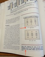
I discovered another use for Blue Tape!!!!

Trying to mark out the outline of each handle on the dark Jarrah with a knife created a line that was impossible to see. The knife would wander with the grain, and when it came time to chisel to the line, the wood would splinter and tear away.

Using Blue Tape not only aided in seeing the outline clearly, but it held the wood fibres securely while they were chiseled.

In the picture below a square is used to ensure each handle is positioned squarely and exactly at the same distance from the end of the drawer front …

FittingHandles_html_f36291f.jpg


Now mark the sides with a knife …

FittingHandles_html_749c6a41.jpg


Here you can see (on the left) that I correct a marking. No matter – this will be removed along with the waste.

The waste is removed with a router, again freehand, and as close to the lines as I dare go.

FittingHandles_html_668ad84d.jpg


The remaining waste is removed with a wide chisel.

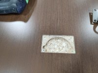
Once this is done, recesses are required for the hinge bar on each side, and a little extra depth was created with a gouge for the domed rear …
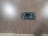
FittingHandles_html_m2345ae73.jpg


The result …

FittingHandles_html_m65734435.jpg


…. Don’t forget to clock the screws. :)

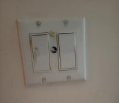
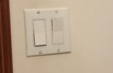
Today ... the two military chests used as a TV stand ..


Regards from Perth

Derek
 
Back
Top