I've just retrofitted Kapex KS 120 REB with Makita XGT LED module.
Of course all this kind of modifications void warranty.
Excuse my poor English.
What you need:
Makita LED circuit, part number: 620F05-6
Adjustable Step Up Voltage Regulator: MT3608
In order to install LED circuit, you will need to remove both lasers from Kapex. They are expensive AF, so be careful not to damage them.
Remove upper plastic cover from the motor (5 Torx T15 screws).
Remove green push lever for around speed dial, disconnect brown, black and white wires from the motor.
Gently rise the electronic module from its place until you see two small, white sockets; disconnect them.
Now take out electronic module. At the bottom there are two identical connectors for both lasers. Disconnect them.
On the right side, underneath the motor unscrew one silver Pozidriv 2 screw (it retaining translucent laser cover). Push in front of the laser cover and pull it out.
Remove left plastic blade cover (T15 screws and 1 hex bolt). In order to get to the hex bolt pull the plastic bumper out. Dust port has 2 screws - unscrew only the one closer to the handle and the whole dust port with cover comes out.
Underneath the cover there are 3 springs, so be careful.
Unscrew 2 small hex bolts holding the lasers.
Remove galvanised metal bracket.
Cut the plug from one of the lasers.
Solder the plug to a 20 cm/8 inch long piece of 0,5 mm2/20 AWG twin-stranded wire. Use red/black wire. Red is "+", black is "-".
Solder the wires with the plug to the IN side of the voltage regulator. Soldier + and - correspondingly.
Cut the plug from Makita LED circuit.
Solder Makita LED circuit to the OUT side of the regulator. Solder + and - correspondingly.
Plug the newly created module into the Festool main electronic module. Test it.
If all works correctly, put Festool electronic module into its place.
Connect all the cables that you disconnected. Remember about proper cable management.
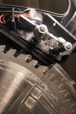
Festool lasers were placed on two rods.
Put heat shrink tubes on these rods.
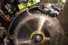
Position the LED module on these rods so that a small hole and a notch in PCB are directly above saw blade.
Glue the LED circuit into place with two drops of CA glue.
Test the shadow line. If OK, use some elastic adhesive to fasten it permanently.
Alternatively you can use plastic spacers on the rods to position the LED circuit.
Screw in two small HEX bolts at the end of the rods.
Put the cover back.
Enjoy your new mitre saw.