KS 120 EB Kapex motor wiring

Illukas

Member
Joined
Aug 24, 2014
Messages
5
Hi! Could any Kapex owner quickly pop the motor cover (just a couple of TX20 bolts) and snap a picture of how the wires are routed?

I stupidly took mine apart to give it a thorough cleaning and thought I'd remember how it was wired, but didn't.
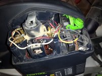
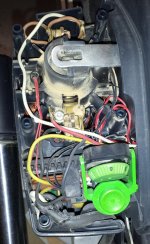
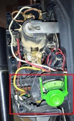
Here's what I have so far, but this might be incorrect.
IVOTVve.jpg
 
Might be of help to somebody, here's what I know so far:

  • Looks like a single-phase commutator motor. Nothing fancy. This means the armature (brushes) and the stator have to be in series.
  • Because its a commutator, it needs that 0.22uF capacitor between the brushes to supress noise. It'll work without it too.
  • Might be wrong here, but seems that the blue wire and the short black wire coming off the PCB are phase and neutral respectively.
  • Yellow and red are normally open. When the switch is depressed - closed.
  • White and red, both coming out of the switch, seem to be connected all the time. Can't say for sure if they're supposed to be.

Fiddling around with the wires, I managed to spin the motor and trip a circuit breaker. But that at least shows that there are no open windings in the stator and armature. She might work yet!

A proper wiring diagram or just a picture would be really helpful though.
 
Thanks a bunch ccmviking.

Looks like the US version doesn't get a supressor cap. I wonder if its got something to do with the lower voltage or just that EU regulations don't apply. I'm no scientist.

In any case, I'll give it a shot tomorrow and see if she fires up.
 
It works, but still trips the circuit breaker. Seems that the leads coming off the board that connect to one of the stator windings are shorted. Not willing to shell out €300+ for the board just yet, so the plan is to clean off the compound to see if it can be fixed. If not, theres always the option to chuck the board and make the saw run on full power constantly. (Without the lasers then.)
 
The local Festool service sent over a schematic for the motor wiring. Turns out that the 110v and 230v saws are wired differently. After correcting the wires, sure enough the saw works without tripping any circuit breakers, but the whole motor overheats in about 10 seconds which implies shorted rotor windings.

The short measured on the PCB was due to incorrect wiring. Actually correct leads coming off the board have >1M ohm resistance between them.

Illukas said:
It works, but still trips the circuit breaker. Seems that the leads coming off the board that connect to one of the stator windings are shorted. Not willing to shell out €300+ for the board just yet, so the plan is to clean off the compound to see if it can be fixed. If not, theres always the option to chuck the board and make the saw run on full power constantly. (Without the lasers then.)
 
Hi. Could any Kapex owner snap a picture of how the wires are routed on speed control panel[marked in the red square on the picture]? Or maybe anyone haas wire schematic for this tool?

Many thanks.

P.S. I apologize for my English
 

Attachments

  • kapex2.jpg
    kapex2.jpg
    289.1 KB · Views: 2,252
Unfortunatelyi did not take any photos of that part of disassembling my Kapex last week, but I did remove the speed control.  What part are you having problems with?  On my US version Kapex, i disconnected the little red wires from the end opposite the speed control.  The two heavier of the black wires on the speed control were left attached to the speed control, they have spade lugs that pull straight up.  The thinner black wires were on a white connector on the speed control.  Pulling ithe speed controller gently straight up an inch allows access to the connector.  At this point you can pull the controller farther out.  Now you can unplug the yellow wire, also with a spade connector.  The wires for the lasers connect to the bottom of the speed controller .  Let me know if i can help clarify anything.

-Eric
 
Back
Top