Wooden Skye
Member
- Joined
- Mar 6, 2012
- Messages
- 1,145
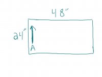
I have been looking at different threads about making an MFT top for an assembly table. I have a few questions about the LR32. The top will be 22" x 32". So here are my questions and a crude diagram.
1) do you always need to use the end stops (16 or 32 up and out)?
2) does any one know what the spacing is between each hole on the Holey rail?
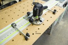
3) with the base plate and OF 1400 on the rail, does this create 96 mm spacing if you used rail dogs and inserted in first row of holes drilled?
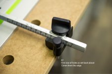
4) to achieve the first row of holes, would setting guide rods to 96mm do the trick?
5) in the attached drawing, if I started at A and bored the holes going in the direction of the arrow, when it go to the opposite edge, do I need to rotate the rail and repeat process in question 4 or do I also need to rotate the work piece?
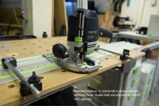
I will clamp the rail and use the 20 mm hinge boring bit. I know this is shop furniture and maybe I am suffering from paralysis by analysis, but this is a good test for first use in my opinion.
Sorry for the long winded post.
Bryan
1) do you always need to use the end stops (16 or 32 up and out)?
2) does any one know what the spacing is between each hole on the Holey rail?
3) with the base plate and OF 1400 on the rail, does this create 96 mm spacing if you used rail dogs and inserted in first row of holes drilled?
4) to achieve the first row of holes, would setting guide rods to 96mm do the trick?
5) in the attached drawing, if I started at A and bored the holes going in the direction of the arrow, when it go to the opposite edge, do I need to rotate the rail and repeat process in question 4 or do I also need to rotate the work piece?
I will clamp the rail and use the 20 mm hinge boring bit. I know this is shop furniture and maybe I am suffering from paralysis by analysis, but this is a good test for first use in my opinion.
Sorry for the long winded post.
Bryan