MB 40 Vacuum base modification

fritter63

Retailer
Member
Joined
Jan 19, 2011
Messages
1,619
Location
Central Coast, California
Well, I tried......

Got it in my head that I had to try making a vacuum base for the MB-40.

Thought that I could get it to hold itself down using the suction from the dust hose while still picking up sawdust from the drilling operations. My inspiration here is the D-27 BSD (Drilling dust guide). So I modeled up a replacement base (using the MB-40 screw mounts) and included a plenum splitter to redirect some of the suction into the base (similar to the D-27 BSD). I used 1/8" vacuum gasket material for this which I've had success with making vacuum fixtures for the CNC.

Unfortunately, I have score this one a FAIL.

While it does suck itself down with tape over the dust port, it's still very easy to knock it over from the top due to the extreme leverage available. And that of course is where you'd be putting all the torque while in use. Also, when I pull the tape, it just doesn't suck much at all.

If anyone has any suggestions on how to make this better, let me know. The key is to get a good amount of vacuum and a large surface area of the stock exposed to the vacuum (hence my snaking vacuum tunnels). Force is directly proportional to the amount of surface area exposed to the vacuum. Maybe I just need the separator to be tight in the hose adapter (there is a little space on each side).

I should add the OEM base works pretty good with its gripper feet. I just thought it would be cool be able to set it down and held in a random location securely without having to use a second hand.

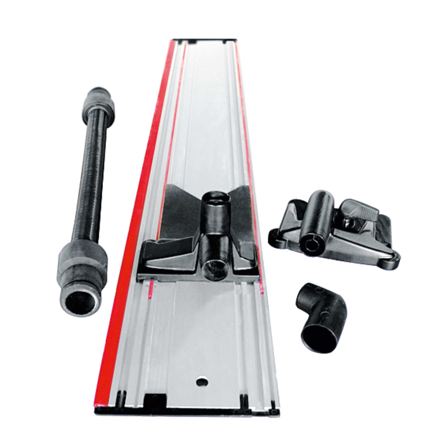
Pictures and video below.

FestoolMB40VacuumBase v28.pngFestoolMB40VacuumBase2.pngIMG_4060.jpgIMG_4061.jpgIMG_4064.jpg


I'm thinking the only physically possible options you have are-

1. Reduce the open area of the dust path, to increase the vacuum inside the chamber- and accept the airflow penalty on the dust capture
2. Extend your O-ring up into the opposite corners if you can, to get maximum spread (not just more total area- but more linear distance between the extremes of that area, will give you some extra counter-leverage in the base)
2a. Could you encircle the entire square with the 1st O-ring, and then add a 2nd O-ring just around the drill bit hole? Make the suction area into a donut. Maximize the area. Vacuum in PSI will give more P if you increase the SI.
3. Give up on the CT and use a vac pump.

Super cool idea, I hope it works out so I can steal it :cool:
Thanks for the input!

2a: considered that. the problem is those front mounting screws. Might be able to just not use those two screws, which would make room for the gasket around the hole. I could also maybe reduce the size of that hole (45mm) make more room, that's a HUGE bit that will never be run in the MB-40.

3. Thought about that, but a second line attached would defeat my simplicity goal!

It might also help to just recess the entire area under the gasket, rather than the channels. that would GREATLY increase the surface area. But then I would have to print with supports, which I've been trying to avoid. Still, that might be the key.
 
I'm not exactly an engineer- but I don't know that more volume in the chamber will help. Routing more of a recess won't change the surface area all that much, and just going off the "per square inch" part of the dimension seems to mean area is the key.

How bout just making the plate larger than the stock foot on the MB40? Like a 12" square. If that ends up being MORE than strong enough, you could trim it back a little at a time, until you find the sweet spot.

And if the 12" square is too weak, then that's your cue to abandon ship LOL
Correct it's not the volume of the chamber it's the surface area exposed to the vacuum.
 
Ok, gonna try this approach with a reduced hole diameter, full gasket, and full recessed area under vacuum. Will need to print it with supports. That'll be ok using PLA and PETG as a support (easy to separate ), but more trick when final one is printed in PETG.

OTH, maybe I'll use ASA (modified ABS) for that. Need to figure out the support material for that. Or maybe start playing around target z axis separation for easy removal.

FestoolMB40VacuumBase v33.png
 
“3. Give up on the CT and use a vac pump.‘

There are a bunch of small battery powered compressors for inflating tires. Should be possible to convert one to a pump.
A small lump of a compressor connected to the MB 40 base via an 1/8th inch tube (when needed) might be worth the trouble.
I agree. I don't think the CT can be used to both hold the MB-40 down and remove the drilling remains. I suggest keeping them separate. That is a vacuum pump to hold the base down and the CT for chip removal.

Bob
 
Ok, well that one works a LOT better just as a hold down, but still useless when you untape the port for dust collection.

Will continue to noodle on this.

Off to L.A. for the weekend and eventually Disneyland. Maybe I'll be inspired.....(will be hanging with an Imagineer no less).

IMG_4071.jpgIMG_4072.jpgIMG_4073.jpg

 
Checkout what Mafell does for their Aerofix. They manage to supply enough vacuum to hold a 3' rail to a surface while also evacuating dust from a MT 55 saw.
OK, yeah, they split the suction hose with a "Y". Was thinking about that too but I couldn't convince myself it it would work any different. That would be pretty easy to print as well.
 
I wonder if you could encircle the cutting area with the vacuum, like on the BSD where only the drill bit is what penetrates the vacuum? Like how the suction ring on the OF1400 encircles the bit. Perhaps this might maintain the suction to both hold the 40 and take in the dust.
 
I wonder if you could encircle the cutting area with the vacuum, like on the BSD where only the drill bit is what penetrates the vacuum? Like how the suction ring on the OF1400 encircles the bit. Perhaps this might maintain the suction to both hold the 40 and take in the dust.
That’s what I did with the last iteration (pictured above).

Gonna try extending the plenum splitter as a complete tube
 
Back
Top