MFT/3 Guide Rail Supports are sloppy

RuhiA

Member
Joined
Feb 19, 2011
Messages
13
Just purchased an MFT/3 table with with accessories primarily to cut sheet material with repeatable length and squareness.  Went through the relatively simple setup process after watching few examples of "how to" videos. All good but there is something puzzled me. The guide rail supports are too sloppy. When you raise it from the squared to fence rail position, it has the tendency to wonder left or right, positioning the tab engaging the guide rail moving a good 2mm resulting a skewed angle for the guide rail. I have tightened the two screws of the cam to ensure that the sliding part engages the plastic frame underneath well but still not satisfactory. The sliding metal part has slightly angles sides to hug the matching angled frame underneath but appears to be stamped too wide, allowing to move side to side. Any suggestions how to achieve a repeatable squareness without adjusting the fence every time I change the cut material height?


Attachments

  • IMG_3474.JPG
    IMG_3474.JPG
    92.4 KB · Views: 720
  • IMG_3476.JPG
    IMG_3476.JPG
    63.1 KB · Views: 605
Look at a product called a SlopStop. It makes the side to side movement of the rail essentially go away. I think it cost $25 USD.
 
I have to admit, I did not expect so many results when I searched it...  [eek]

But, what I am describing is not the tolerance in between the tab and the guide rail. That should not be there either but I am talking about the side side motion of the supporting slide itself. Not related to the "tab".
 
You just have to be conscientious when you change the height adjustment, and make sure it's laying flat on the workpiece.  If you're cutting narrow stock, it helps to have a piece of scrap the same thickness near the front of the rail so it doesn't rest crooked.

But you're right, there is room for error when you are changing heights, even when you are careful.  This is one of the reasons why I like to square up my fence and rail with a piece of 3/4ply and a scribe line, as opposed to the fence flat on the MFT itself.
 
Are you saying when you raise the rail it can move left or right?
If so I too find that troubling... Essentially it means one needs to check square every time the elevation is altered.
I just wiggle it to find the center and consider "OK enough".
 
Edward A Reno III said:
... there is room for error when you are changing heights, even when you are careful.  This is one of the reasons why I like to square up my fence and rail with a piece of 3/4ply and a scribe line, as opposed to the fence flat on the MFT itself.

Holmz said:
Are you saying when you raise the rail it can move left or right?
If so I too find that troubling... Essentially it means one needs to check square every time the elevation is altered.
I just wiggle it to find the center and consider "OK enough".

In order to clarify: Guide rail is the long piece from front to back where the user ride the saw/router; guide posts are the ones on the front and rear to support and align the guide rail.

Please look at the pictures attached. One is when the rail support is at the near lowest position (guide rail would be resting on the face of the table), the other when the guide support is raised to keep the rail at a higher position to fit a thicker stock under the guide rail.
When the support is raised there is more then 2mm side side side movement. Considering the cutting width is about 750mm, 2mm off the square is not just a simple tolerance error.
Is there solution for when the the height of the rail is being changed, the support will move up and down without wondering side to side to get a square cut without squaring the fence? Besides, it would be extremely difficult to square the fence to the rail when it the rail is not near the table surface.
I have not seen/read in any place informing the user that every time you change the material thickness, you need to re-calibrate your table.
 
My rail seldom comes down exact before it contacts that little tab.  If the tab is too low, the rail will not be purficly square. As long as the tab is set to the proper height, the rail settles into alignment perfectly.  I also picked up a couple of little plastic do-dads that fit into the slot on underside of the rail.  I had noticed wear in the slot where the vertical tab set into the underside of the rail.  There was a conversation here on the FOG a while back about that very problem and one of the vendors came up with that little plastic insert.  I have had that insert installed for, I think, several years and there is no more slop.  The plastic seems quite stable as there is no sighn of undue wear from many contacts with that tab. 

If I do not have that slide with the tab set just right, the cut could be anywhere.  I almost never find my rail coming down exact if that tab is not set at proper height.  I am sure it is based on geometry.  The hinged tab is probably not dead on to the .000º If one depends on the hinge being set perfect, the free end could be inches off.  When the inge is set against the stops in the MFT frame and the free end has been set properly against the frame stops on the there end of the rail, and the slides at both ends of the rail are set at the proper height, the rail should come down in proper alignment every time.  I check my rail for square nearly every time I start work and sometimes, with my small work space, when I bump either nd of the rail, I will check for square.

Tinker
 
If you set the height of the rail when it is lying on a piece of material that you are going to cut near the tab, it has to be lifted until it is in the groove and square to the rail. At this point the tab slide doesn't move from side to side because it is being kept square to the rail.

The same applies to the hinge end. You drop it onto the material that you are going to cut and while holding it flat clamp it.

If you follow this procedure the rail always finishes square to the fence, assuming that you have the tabs correctly set in the first place.

If your rail shows any wear where the tab engages it just move your rail backwards or forwards to a new spot with no wear.
 
Bohdan said:
If you set the height of the rail when it is lying on a piece of material that you are going to cut near the tab, it has to be lifted until it is in the groove and square to the rail. At this point the tab slide doesn't move from side to side because it is being kept square to the rail.

The same applies to the hinge end. You drop it onto the material that you are going to cut and while holding it flat clamp it.

If you follow this procedure the rail always finishes square to the fence, assuming that you have the tabs correctly set in the first place.

If your rail shows any wear where the tab engages it just move your rail backwards or forwards to a new spot with no wear.

I think in replies people keep misinterpreting the OP. He is talking about sloppiness and lack of repeatability of positioning rail support relative to the table, NOT the guide rail relative to support.
 
I've noticed this too.

My work around is to do the initial squaring and then mark the first piece to be cut to verify everything is aligned before cutting.

The MFT seems to hold its setup pretty well once set for a cut, but it isn't the kind of precision tool that I would trust to adjust accurately and repeatably. It just isn't that kind of tool.
 
Svar said:
I think in replies people keep misinterpreting the OP. He is talking about sloppiness and lack of repeatability of positioning rail support relative to the table, NOT the guide rail relative to support.
Correct. Therefore, I carefully used "guide rail" and "guide post" explicitly while I was describing but... :)
The tab which goes into the guide rail is engaging the grove under the guide rail really nice, as a matter of fact. No side to side to require any gizmos to further prevent relative motion in between the support and the rail. It is just fine. As it wears of, as someone suggested, just positioned hte rail few millimeters in either direction.

Shane Holland said:
FYI... We have the Slop Stop.
The issue that I am raising can not be addressed by the slopstop.

jamanjeval said:
I've noticed this too.
The MFT seems to hold its setup pretty well once set for a cut, but it isn't the kind of precision tool that I would trust to adjust accurately and repeatably. It just isn't that kind of tool.
For the same material thickness, during the same session of cutting, I expect to be reliable and repeatable but it is not the case when you have to make changes or remove the supports and "slap it back" to where you were, as it was advertised

waho6o9 said:
Exactly why I use rail dogs :)
Meaning the MFT/3 cannot do what it was designed and sold for as it is marketed.

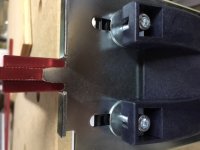
Here is what I did to further understand. I took the supports apart after calling the Festool CS to be told it is what it is and I have the option to return it.
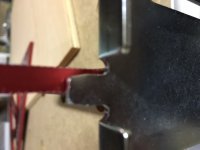
The sliding metal support is wider than the plastic frame. When the bolts tightened to a point that it should pull the metal support to the face of the plastic frame, it would be expected to see they mate well and there is not lateral translation/rotation. It does pull the two surface together but since the sloping edges are flaring out too much, the edges don't mate well. Placed the metal support in my bench vise and tightened ever slightly. Repeated till I got a "snug" fit allowing to slide the support freely. Now, I can slide it up and down and get nearly no lateral sloppiness. I will do the same with the rear support as well.

Note: When I spoke with the Festool CS, suggested that this could be easily addressed if some to check the shaping stamp mold for the support piece to create the channel like shape. He said he would pass it on. I think the stamping mold is made about at least 1-2mm too wide. My two cents, just in case if anyone is reading. ;)
 
This isn't a new issue. My MFTs are ten years old this year, and even the hardware on those older MFT-1080 and MFT-800 models have the same exact issue.
 
Corwin said:
This isn't a new issue. My MFTs are ten years old this year, and even the hardware on those older MFT-1080 and MFT-800 models have the same exact issue.
It is a new issue to me and to be honest I was pretty surprised and disappointed to find out. I watched and read countless number of MFT/3 reviews. Not a single mention of this except in one, in a Festool workshop for MFT/3, the instructor mentions the need to tighten the two bolts holding the lever to prevent the support sliding down.
It can be addressed so easily but maybe no Festool user/buyer wants to admit that they bought a defective product which does not do what it meant to without additional aftermarket parts or solutions.
If a small fraction of the owners made the call, it would have been corrected by now and there would be new and improved rail support. Wishful thinking on my part?
 
[member=10601]RuhiA[/member] Read my previous post #8 again very carefully and you will see that the fault that you are describing is not really a problem if the MFT guide rail supports are used correctly.
 
Bert Vanderveen said:
... must have been caused by use.
I'm going out on a limb here to suggest that reading the original post would help to provide relevant and useful input.
 
IMO that part of the MFT system is a bit of a weak design and a bit wobbly for the very accurate repeat cut needs of us cabinetmakers. for other trades/needs it seems to work ok.

i have basically finagled my setup to avoid this- qwas dogs to register the fence, then set the rail as accurately as possible at 19mm or 3/4" height for cutting my panels. since the huge majority of my cuts are of that same thickness, i end up having to change the rail height very rarely. i even slip in extra stock to make up the height difference if i have to cut just a few thinner pieces like 1/2" or 1/4." imperfect, but it works, and is part of my overall system of making casework without a table saw with only a slight time penalty (and with big safety, space, cost, etc benefits that, in the big picture, surpass the small time penalty).

i drew up a redesign for that part of the mft system that would use a machine screw for fine tuning the 90 deg setting, for use by cabinetmakers who need the accuracy for building euro box cases, where you can't have compounding error, but never got around to producing it…

you might look up Guido Henn videos, he has a simple 90 deg dedicated (as in, not adjustable to other angles) setup that would be a breeze to make and would presumably need no adjustment ever.

i still like the MFT table in spite of this weakness, as all the other functionalities are very good, and new uses for the hole set and other features continue to come up the more you use it.
 
Back
Top