MFTC portable workshop

Tom,
Nice work on the MFTC!  Thanks for sharing the pictures.  Welcome to FOG.

Schoutedentom said:
Hi all,  [big grin]
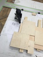
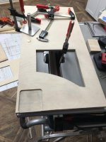
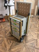
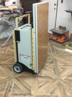
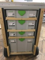
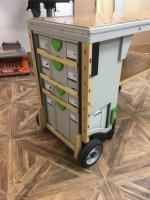
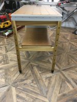
As a new member on the forum, I would like to share the MFTC version I made thanks to the plans of Tim!
I did not yet inserted T-tracks or slots in the legs. Some finishes for later :-)

DSC_7858_WEB.jpg


DSC_7859_WEB.jpg


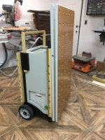
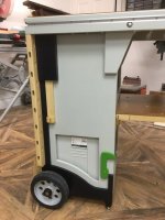
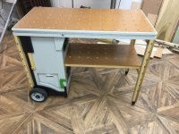
I made a small modification to fit my CTL26 underneath the shelf. The space for tools get's a little bit smaller, but it does work fine to fit the tracksaw!
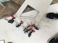
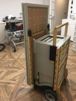
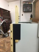
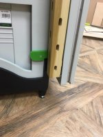
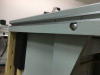
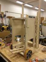
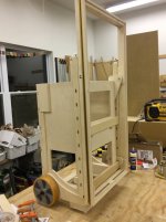
On the handle I've added 2 wooden lockers to push the cart without moving the handle.
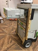
And on the drawers I basically did the same, to prevent the drawers from getting out of the cart (I didn't add the magnetic locks)

Regards
Tom
 
Welcome. Very nice work on the table!  I just bought the plans from Tim last week.

Did you bore the holes in the top yourself?

Best,
Adam
 
Hi,

I just got into woodworking, and building the mftc will by my first project so I have a work table to do my future projects.  I am building to Tim's plans, except for the base of the carcass where I am using my own axle so I can avoid the box at the bottom and keep the entire carcass for my systainers.  I only get a a few hours in a week to build this as we have a toddler and another one on the way, but I really enjoy it.  I downloaded sketchup and designed my own axle, bought a 20mm axle from amazon, and a friend of mine with a metal shop mounted it onto a 1/4" plate for me (he even rounded the corners so it would be easier for me to route and inlay, he's a GOOD friend!).  I routed about an 1/8" into both pieces of wood and sandwiched the wood together with clamps and screws.  I used gorilla epoxy on the bracket and the routed area, then I used titebond 3 on the wood to wood areas.  This was my first "glue up," and it was pretty funny as I quickly discovered that someone was right when they said "you can never have enough clamps" and as I realized i put way to much glue in as it came oozing out from all sides.  Luckily my wife and daughter decided pay me a visit at that very moment to see what I was up to, they thought it was hilarious!  Using most of these tools is a first for me so I am taking my time and I am assuming any error that occurs while using them is my own as I try to get used to them.  I did as much research as I could prior to starting this hobby and htis project and sites like this one were a great a resource, so thank you for anyone that has posted.  So far I have to say the domino and the of1400 are my favorite followed by the ts55 and the carvex.  Below are some pictures of my progress so far.
 

Attachments

  • Capture.jpg
    Capture.jpg
    41.8 KB · Views: 2,518
  • IMG_1853.jpg
    IMG_1853.jpg
    104 KB · Views: 1,571
  • IMG_1855.jpg
    IMG_1855.jpg
    111.2 KB · Views: 2,009
  • IMG_1857.jpg
    IMG_1857.jpg
    141.8 KB · Views: 1,297
  • IMG_1859.jpg
    IMG_1859.jpg
    163.1 KB · Views: 1,189
  • IMG_1861.jpg
    IMG_1861.jpg
    118.4 KB · Views: 1,194
  • IMG_1911.jpg
    IMG_1911.jpg
    133.8 KB · Views: 1,565
  • IMG_1913.jpg
    IMG_1913.jpg
    91.9 KB · Views: 1,662
  • IMG_1914.jpg
    IMG_1914.jpg
    125.4 KB · Views: 1,702
  • Capture.jpg
    Capture.jpg
    41.8 KB · Views: 1,354
  • IMG_1852.jpg
    IMG_1852.jpg
    93.1 KB · Views: 1,489
  • IMG_1851.jpg
    IMG_1851.jpg
    88.3 KB · Views: 1,800
  • IMG_1816.jpg
    IMG_1816.jpg
    72.5 KB · Views: 2,624
  • IMG_1819.jpg
    IMG_1819.jpg
    160 KB · Views: 2,232
  • IMG_1822.jpg
    IMG_1822.jpg
    96.9 KB · Views: 2,014
  • IMG_1823.jpg
    IMG_1823.jpg
    111.4 KB · Views: 1,928
  • IMG_1835.jpg
    IMG_1835.jpg
    93.4 KB · Views: 1,917
  • IMG_1837.jpg
    IMG_1837.jpg
    145 KB · Views: 2,004
  • IMG_1838.jpg
    IMG_1838.jpg
    107.7 KB · Views: 2,190
  • IMG_1843.jpg
    IMG_1843.jpg
    76.9 KB · Views: 1,665
  • IMG_1846.jpg
    IMG_1846.jpg
    78.6 KB · Views: 1,568
more photos
 

Attachments

  • IMG_1921.jpg
    IMG_1921.jpg
    131.5 KB · Views: 1,839
  • IMG_1920.jpg
    IMG_1920.jpg
    95.8 KB · Views: 1,435
  • IMG_1919.jpg
    IMG_1919.jpg
    123.7 KB · Views: 1,477
  • IMG_1918.jpg
    IMG_1918.jpg
    106 KB · Views: 1,438
  • IMG_1917.jpg
    IMG_1917.jpg
    107.9 KB · Views: 1,568
  • IMG_1916.jpg
    IMG_1916.jpg
    177.1 KB · Views: 1,438
  • IMG_1915.jpg
    IMG_1915.jpg
    116.3 KB · Views: 1,507
I really liked the axil solution with the metal plate welded on to the shaft and how you fixed it in to place. a very nice job.
I wouldn't worry about the squeeze out, that happens to the best of us. Especially when you are using a new type of glue.

I was wondering for those who want to keep their MFTC as light as possible.
So this is a question for all those engineers out there.

If one used a slightly thinner base plate and routed the plate flush in to the inside and screwed it in to place and the axil passed through the side in a tight hole. Would this have the same strength as this doubling up on the outside?

Just my  [2cents]

Pip
 
ART at WORK said:
If one used a slightly thinner base plate and routed the plate flush in to the inside and screwed it in to place and the axil passed through the side in a tight hole. Would this have the same strength as this doubling up on the outside?

Just my  [2cents]

Pip

I think you could safely go to 1/8-inch plate in this design without issue, maybe even thinner as long as the weld area can handle the load.  If we can assume the welded material will not fail - sandwiching the plate between the pieces of ply prevents the plate from deflection as pressure is put on the shaft.  Screwing a piece of plate to the inside of the ply removes that support and now the deflection is only countered by the screw/screw placement.  That being said, I think 3/16 plate would work on the inside (given the likely load if it were my cart) and lighter carts might get away with 1/8-inch. 

If lighter was the goal, I'd use aluminum in either design or a combination if using a fastener in place of a weld.
 
Nice work MJH2157.  Since you shared yours, I figured I'd share my solution.  I chose a slightly different approach mostly because of the tools I have available.  I machined some hubs out of 6061 aluminum Rod I had in the shelf.

6e7b16eae82bba212e4b49bcd1add4e2.jpg


I then laid out the spindle design for the wheels I'm using. 

515a06f96cf174519c0f79ad20553416.jpg


After a little lathe time, I have the first spindle.

5ea0e1f6c66cc159b5efc73e297a6218.jpg


Spindle fits into the hub which allows me to make a different spindles should I choose other wheels in the future.

071ad72a2662fa6ffc32d90dd6c8d4ed.jpg


This mockup in the wheel shows how I retain the spindle in the hub.  The 1/2-inch bolt not only retains the spindle, it adds strength so the aluminum isn't taking all of the load.

a1bfab6ede92dd913365ab97a675c6e2.jpg


To install it, a 1 1/8 (IIRC) forstner bit is used to a 1/2-inch depth and I'm starting with screws as the fasteners.  If screws don't end up strong enough, I can always use a backing plate I can recess inside the box/casing.

2ecc9ba0ebbdd0966a15650add44254e.jpg


An interesting twist would be to combine the two designs.
 
Wow, you are talented!  Thank you for sharing that, I'm seriously impressed by the quality of your work!  It's funny because when I was researching building my mftc I saw you had pictures of your two carcasses and I noticed you didn't have the wooden drawer which I didn't want, but the pictures stopped there.  I wondered what your solution was at the time as no one else appeared to do all systainers.  I'd really like to pick up metal work and milling in the future and meld it into my woodwork more. Your posts are a great inspiration.  I love the way you threaded the end of the axle, nice touch!  May I ask, how did you attach the green latch at the bottom of the carcass opposite the wheel, so that it can turn up and down?  I was thinking that if I screwed it from inside the carcass that it would eventually unscrew itself.

Pip,

Thank you as well for your kind comments! With regard to my axle setup, I just wanted to clarify for anyone that tries it or a hybrid, when I was working out the fabrication with my friend that fabricated it based on my little drawing, he actually came up with the solution to drill a 20mm hole through the plate, insert the rod in to the hole, and weld it from the back side, so that there would be no weld on the front side to deal with later around the axle that would have resulted in reaming out the back of the hole in the wood later.  The welds on the back side were ground smooth which is much easier to do then it would have been on the front side where you would have a hard time grinding the weld around the axle.

Best Regards,
Matt
 
mjh2157 said:
Wow, you are talented!  Thank you for sharing that, I'm seriously impressed by the quality of your work!  It's funny because when I was researching building my mftc I saw you had pictures of your two carcasses and I noticed you didn't have the wooden drawer which I didn't want, but the pictures stopped there.  I wondered what your solution was at the time as no one else appeared to do all systainers.  I'd really like to pick up metal work and milling in the future and meld it into my woodwork more. Your posts are a great inspiration.  I love the way you threaded the end of the axle, nice touch!  May I ask, how did you attach the green latch at the bottom of the carcass opposite the wheel, so that it can turn up and down?  I was thinking that if I screwed it from inside the carcass that it would eventually unscrew itself.

Best Regards,
Matt

Matt,

Thanks for the compliments.  I very much enjoy machining and, as you pointed out, it can compliment woodworking nicely on various projects.  I intentionally try to cross disciplines whenever I can because l actually prefer the combination and in some cases the precision of machining can simplify and speed things up.

So the real answer on what happens to my MFTC projects is I'm not done yet.  I got sidetracked about the time I posted by house projects and I'm just now getting back to the it.  Unfortunately (or fortunately depending on how you look at it) I always have a dozen projects in flight so I can work on whatever energizes me at the moment.  For the past year or so I've been working on what energizes the Mrs. so I can sleep inside.  :)

Since I enjoy machining so much I plan to make most of the bracketry out of aluminum and extrusions for the frame of the table top.  I have noticed that the base cart (wheels, Systainers loaded, and the shell with slides) is fairly heavy so I'm second guessing my strategy now that I've been able to pull one around.  I can deal with heavy around the shop but if they have to go up the stairs, forget it. 

My plan for the latches was to machine something but now I'm leaning toward the use of a pronged t-nut on the inside and a machine screw to hold on the latch with some thread-lock (blue) to keep the screw from unscrewing itself.  The t-nut can easily be recessed if it ends up in the way or, if I'm lucky, the 1/16th it protrudes won't matter.

I really like your spindle design.  In fact, if the parts were aluminum and the end was threaded, it would be not only simpler than mine to make, but cleaner.  The more I think about it, I'm disappointed I didn't think about it myself and I'm too far to make the switch. 

~ Matt (also)
 
Hi All,

So had a chance to resume work on my mftc today.  Made the legs, glued them up, made all the domino holes in them, radiused the fixed legs, and made my own levelling feet by combining two that I like to get the best of both worlds.  I really wanted something that could be adjusted quickly by hand, could articulate to uneven surfaces, was durable, and and had anti vibe/anti skid pads that wouldn't fall off.  They are really solid and can level over 30mm (i know overkill).  I'm really happy with the way they turned out, which is unusual for me! [big grin]

Anyway, pic below.  Hopefully they are of use to someone.  All I have left now is finish paint/poly and final assembly. 

Best,
Matt


Attachments

  • IMG_4157.jpg
    IMG_4157.jpg
    91 KB · Views: 1,693
  • IMG_4158.jpg
    IMG_4158.jpg
    44.2 KB · Views: 1,441
  • IMG_4159.jpg
    IMG_4159.jpg
    56.4 KB · Views: 1,495
  • IMG_4160.jpg
    IMG_4160.jpg
    45.2 KB · Views: 1,225
  • IMG_4161.jpg
    IMG_4161.jpg
    51.6 KB · Views: 1,342
  • IMG_4163.jpg
    IMG_4163.jpg
    83.4 KB · Views: 1,252
  • IMG_4165.jpg
    IMG_4165.jpg
    78.6 KB · Views: 1,757
  • IMG_4156.jpg
    IMG_4156.jpg
    70.6 KB · Views: 1,125
  • IMG_4155.jpg
    IMG_4155.jpg
    58.6 KB · Views: 1,066
  • IMG_4135.jpg
    IMG_4135.jpg
    47.2 KB · Views: 1,717
  • IMG_4139.jpg
    IMG_4139.jpg
    106.3 KB · Views: 1,326
  • IMG_4140.jpg
    IMG_4140.jpg
    81 KB · Views: 1,455
  • IMG_4145.jpg
    IMG_4145.jpg
    69.4 KB · Views: 1,253
  • IMG_4148.jpg
    IMG_4148.jpg
    94.5 KB · Views: 1,240
  • IMG_4153.jpg
    IMG_4153.jpg
    57.1 KB · Views: 1,180
  • IMG_4154.jpg
    IMG_4154.jpg
    55 KB · Views: 1,096
Man this thread has so much good stuff in it! Glad to see its still alive and growing!
 
Hi,

Received a few emails about my levelling foot and great point about how to lock the systainers in place.  I posted the link for a lock at the very bottom.  Wish I could understand the guy in the video, but his lock is awesome.

Here is a link to the leveling foot::
https://www.amazon.com/Winco-8NTNT-Stainless-Snap-Lock-Non-Skid/dp/B00EI1N2QQ

Here is a link to the plastic leveling foot, don't mind the picture of the angle bracket on the site.  This is the actual product.  Parker leveling foot 21-001:
https://www.hydradynellc.com/product/21-001/leveling-foot

Here is a link for threaded rod:
https://www.amazon.com/gp/product/B00JDU9Z9A/ref=oh_aui_search_detailpage?ie=UTF8&psc=1

Here is a link for threaded inserts:
https://www.amazon.com/gp/product/B002WC8TW0/ref=oh_aui_search_detailpage?ie=UTF8&psc=1

Obviously, you don't have to buy these things at these sites, you should shop around.  Amazon doesn't seem to be the cheapest for industrial parts/machine parts, but you have a starting point on specs. 

If you need anything at all let me know. 

Regarding the bar lock I was just thinking about that the other day, I'm yet to figure that one out.  If you have any ideas I'd definitely be interest.  There was one I saw way back when on this site, but I haven't really delved into how it was done.  It's the best one i've seen, but it also utilizes the wood blocks at the bottom for the wooden drawer.  I don't have that, I ran my systainers down to the bottom.  It's at 8:52:


I'll post this on the general forum too for everyone.

Best,
Matt
 
It took me a crazy amount of time, but I'm finally done with my first woodwork project.  Now I have a workbench to do my future projects.  I learned a tremendous amount doing this workbench and although I found many moments of it to be stressful, it was a very rewarding project. 
 

Attachments

  • IMG_5215.jpg
    IMG_5215.jpg
    81.9 KB · Views: 3,200
  • IMG_5216.jpg
    IMG_5216.jpg
    65.9 KB · Views: 3,732
  • IMG_5217.jpg
    IMG_5217.jpg
    76.5 KB · Views: 2,479
  • IMG_5218.jpg
    IMG_5218.jpg
    46.8 KB · Views: 1,478
  • IMG_5219.jpg
    IMG_5219.jpg
    70 KB · Views: 1,670
  • IMG_5222.jpg
    IMG_5222.jpg
    77.7 KB · Views: 3,275
  • IMG_5214.jpg
    IMG_5214.jpg
    70.2 KB · Views: 3,039
  • IMG_5213.jpg
    IMG_5213.jpg
    69.8 KB · Views: 2,460
  • IMG_5211.jpg
    IMG_5211.jpg
    60.1 KB · Views: 1,770
  • IMG_5210.jpg
    IMG_5210.jpg
    77 KB · Views: 2,363
  • IMG_5209.jpg
    IMG_5209.jpg
    61.1 KB · Views: 2,705
  • IMG_5208.jpg
    IMG_5208.jpg
    44.2 KB · Views: 1,831
  • IMG_5204.jpg
    IMG_5204.jpg
    86.4 KB · Views: 1,773
  • IMG_5203.jpg
    IMG_5203.jpg
    122.3 KB · Views: 3,202
mjh2157 said:
It took me a crazy amount of time, but I'm finally done with my first woodwork project.  Now I have a workbench to do my future projects.  I learned a tremendous amount doing this workbench and although I found many moments of it to be stressful, it was a very rewarding project. 
Looks great man! Good job! Should serve you well for many years to come!
 
[member=28480]mjh2157[/member] That is a table to be proud of.  Thank you for sharing.  Bill
 
I am in the middle of making my MFTC. I didnt want to start until I solved the wheel/axle, drawer lock, and and t-track hardware issues. I bought the regular Incra T-track for my work top. One issue I noticed is that the t-track is thick enough that  I have to cut entirely through the  1/2" outer plywood of the pivoting work top in order to set it flush. Where this presents a particular problem for me is the slots I cut previously to house one end saw tracks. I would add another layer of 1/2" by 2 inch to the inside of the end where the folding legs are attached and cut my blind slots in that instead of making any slot at that end in the 3/4 " plywood. As it stands now, once the t-track is in place all the screw holes fall in the area of the saw track slots! I am planning to arrange the t-track at that end so that I can put a couple of screws in at each end and in the middle. I thought I might move the t-track groove down on the three sides but then it interferes with the pivot bolts. I thought I could maybe move the groove down to solid wood on the end only, so that it falls below the blind slots I cut at that end, but then the extension tables wouldn't line up. Maybe the best solution is to use two pieces of 3/4" on each side and increase  the width of the legs to match the wider top
 

Attachments

  • MFTC2.jpg
    MFTC2.jpg
    1.3 MB · Views: 4,880
  • MFTC 1.jpg
    MFTC 1.jpg
    1.2 MB · Views: 5,032
Back
Top