My Custom Adjustable Off-Cut Stop For MFT Repetitive Cuts - Now Modified Twice

squarecut

Member
Joined
Dec 2, 2013
Messages
186
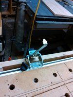
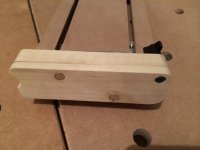
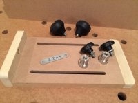
I needed a method of producing repetitive cuts on the off-cut side of my expanded MFT. I have significant MFT real estate on the off-cut side of the cut line on my custom unit so in addition to making narrow off- cuts I can use this custom adjustable stop to cut material up to 20" wide, allowing me to place my work piece on either side of the guide rail cut line as I see fit.
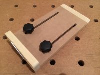
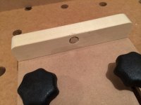
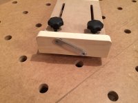
I fabricated this unit out of 3/4" MDF & Poplar and utilized the short Parf Dogs I have in my inventory. I added some small star knobs and a piece of steel strapping from my unknown metal parts box - (that's the box of miscellaneous parts I always think I can put to use one day) That piece was a lucky find for me. I sanded the strapping down on my Ridgid Belt Sander to 2.2mm from 2.25mm. The steel strap substitutes for the kerf thickness of the TS-55 blade and is held in place by rare earth magnets. I installed one rare earth magnet on the reverse side of the stop fence to store the kerf spacer when removed from the front face. This insures that I do not misplace it, or have it possibly end up under the saw blade. I can lock the Parf Dogs to the underside of my winged extension if needed by utilizing the knobs from my Festool Clamping Elements, but so far that has not been necessary.

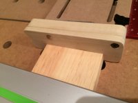
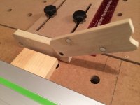
Photos 1 through 6 are views of the unit
[attachthumb=1]  [attachthumb=2]  [attachthumb=3]  [attachthumb=4]  [attachthumb=5]  [attachthumb=6]

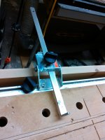
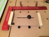
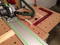
Photo 7 shows the squaring verification process utilizing my Woodpeckers 18" square & two Qwas dogs to insure the Stop's fence is parallel to the guide rail.
[attachthumb=7]

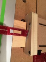
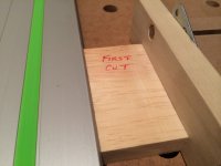
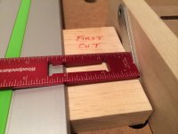
Photo 8 shows the initial setting of the cut by measuring from the splinter guard edge to the Stop fence with the kerf spacer attached.
[attachthumb=8]

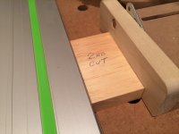
Photos 9 & 10 show the stock advanced to the stop fence with the kerf spacer removed.
[attachthumb=9]  [attachthumb=10]

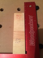
Photo 11 shows the two pieces of stock dead-on identical in width.
[attachthumb=11]

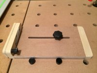
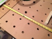
Photos 12 & 13 show overall layout & the 20" cut capability
[attachthumb=12]  [attachthumb=13]

Please Note -
On 7/31/15,  I modified this unit to eliminate the possibility of binding & kickback - See Reply # 15

On 8/23/15,  I modified this unit to make it self-squaring - See Reply # 16
 

Attachments

  • ROCS-01.JPG
    ROCS-01.JPG
    1.7 MB · Views: 4,039
  • ROCS-12.JPG
    ROCS-12.JPG
    1.7 MB · Views: 1,448
  • ROCS-13.JPG
    ROCS-13.JPG
    1.8 MB · Views: 3,252
  • ROCS-11.JPG
    ROCS-11.JPG
    564.1 KB · Views: 1,319
  • ROCS-10.JPG
    ROCS-10.JPG
    1.4 MB · Views: 1,373
  • ROCS-09.JPG
    ROCS-09.JPG
    1.3 MB · Views: 1,436
  • ROCS-08.JPG
    ROCS-08.JPG
    1.5 MB · Views: 2,102
  • ROCS-07.JPG
    ROCS-07.JPG
    1.8 MB · Views: 2,076
  • ROCS-06.JPG
    ROCS-06.JPG
    1.6 MB · Views: 2,133
  • ROCS-05.JPG
    ROCS-05.JPG
    600.1 KB · Views: 3,738
  • ROCS-04.JPG
    ROCS-04.JPG
    1.6 MB · Views: 1,120
  • ROCS-03.JPG
    ROCS-03.JPG
    1.5 MB · Views: 1,175
  • ROCS-02.JPG
    ROCS-02.JPG
    1.5 MB · Views: 1,909
[member=26002]squarecut[/member] - great idea! Simple and effective.

Any issue (or concern) with kickback since the off-cut is trapped against the guide?

RMW 
 
Richard/RMW said:
[member=26002]squarecut[/member] - great idea! Simple and effective.

Any issue (or concern) with kickback since the off-cut is trapped against the guide?

RMW

I have cut about 25 off-cuts of varying lengths so far and have had no problems to date.
 
I'm curious why you wouldn't have mad the lower edge long enough to meet with some dogs parallel to a bottom edge to get a natural square?

That said, now I'm visualising another variation with a fixed dog hole and an arc [big grin]

Cool [thumbs up]
 
Kev said:
I'm curious why you wouldn't have mad the lower edge long enough to meet with some dogs parallel to a bottom edge to get a natural square?

That said, now I'm visualising another variation with a fixed dog hole and an arc [big grin]

Cool [thumbs up]

Kev

The reason I did not do that is because you thought of it, not me. [doh]  Good idea! That would have worked and I could have eliminated one Parf Dog & one slot. As for a fixed dog hole, if I understand you correctly, that would not be as flexible and would limit me to the 96mm repeat on the left to right adjustment of the Stop.

Bob
 
squarecut said:
Kev said:
I'm curious why you wouldn't have mad the lower edge long enough to meet with some dogs parallel to a bottom edge to get a natural square?

That said, now I'm visualising another variation with a fixed dog hole and an arc [big grin]

Cool [thumbs up]

Kev

The reason I did not do that is because you thought of it, not me. [doh]  Good idea! That would have worked and I could have eliminated one Parf Dog & one slot. As for a fixed dog hole, if I understand you correctly, that would not be as flexible and would limit me to the 96mm repeat on the left to right adjustment of the Stop.

Bob

Absolutely agree. I'm thinking a second jig that effectively behaves as a protractor. I have a bad habit of going from one to seven, without explaining my thinking from two through six [embarassed]

I've had a stream of thoughts since then too. In fact something stupidly simple, but I'm not sure MDF would be stable enough. Imagine yours, with the entire rectangle cut out of the middle, slightly larger and with a stepped edge. Now picture a circle with a reverse of the stepped edge fitting inside the rectangle ... clamping the jig down down through two dogs in the circle.

This would allow complete rotation and depth adjustment. It could even be calibrated so a depth scale could read against the degree scale (but that's probably getting a bit too sophisticated).

Anyway .. I think you've seeded some very interesting thinking.
 
Kev said:
squarecut said:
Kev said:
I'm curious why you wouldn't have mad the lower edge long enough to meet with some dogs parallel to a bottom edge to get a natural square?

That said, now I'm visualising another variation with a fixed dog hole and an arc [big grin]

Cool [thumbs up]
I like that idea. I might try that.
Kev

The reason I did not do that is because you thought of it, not me. [doh]  Good idea! That would have worked and I could have eliminated one Parf Dog & one slot. As for a fixed dog hole, if I understand you correctly, that would not be as flexible and would limit me to the 96mm repeat on the left to right adjustment of the Stop.

Bob

Absolutely agree. I'm thinking a second jig that effectively behaves as a protractor. I have a bad habit of going from one to seven, without explaining my thinking from two through six [embarassed]

I've had a stream of thoughts since then too. In fact something stupidly simple, but I'm not sure MDF would be stable enough. Imagine yours, with the entire rectangle cut out of the middle, slightly larger and with a stepped edge. Now picture a circle with a reverse of the stepped edge fitting inside the rectangle ... clamping the jig down down through two dogs in the circle.

This would allow complete rotation and depth adjustment. It could even be calibrated so a depth scale could read against the degree scale (but that's probably getting a bit too sophisticated).

Anyway .. I think you've seeded some very interesting thinking.
 
Festool used to have us covered on this functionality.  Back in the 1080 days they offered a fixture that provided this exact functionality.

I don't even know what this is called.  I got it back when I bought my MFT.  I saw it and wanted it and my dealer didn't have one in stock so he just gave his demo to me.  He never sold one.

[attachthumb=1]
[attachthumb=2]

As you can see, it tilts up so binding or kickback is not an issue cause the workpiece is never trapped.  A Homemade jig could incorporate the tilt up feature if binding ever did become a problem.

It's designed to be a crosscut aid and the stop is convex so only a single point touches the workpiece.  So squaring has to be accomplished some other way. The thing really works great. 

I don't think there is an equivalent for the MFT/3.  And that points to a sad reality.  Festool has missed the boat on developing and marketing useful add-ons.  There could be a whole fleet of gadgets.
 

Attachments

  • stop2.jpg
    stop2.jpg
    740.2 KB · Views: 910
  • stop1.jpg
    stop1.jpg
    680.7 KB · Views: 1,622
[member=2018]fshanno[/member]
Well, cost is relative. I do woodworking and metal working and think $50 is relatively cheap. Between ordering parts on the internet, fabbing other necessary metal items, fabbing the wooden items and assembling and fine tuning the hardware, a guy's got 3-4 hours into the project. On a per hour basis, McDonalds pays more.
 
Cheese said:
[member=2018]fshanno[/member]
Well, cost is relative. I do woodworking and metal working and think $50 is relatively cheap. Between ordering parts on the internet, fabbing other necessary metal items, fabbing the wooden items and assembling and fine tuning the hardware, a guy's got 3-4 hours into the project. On a per hour basis, McDonalds pays more.

True.  Your point is well taken.  But it leads to another question that I think is kind of interesting.

Isn't it curious that Festool is still manufacturing a fixture for the 1080 that has no equivalent for the MFT/3?  What is  that about?  Or is 488564 out of production and what we're seeing is just old stock that has never sold?  In which case my dealer was not the Lone Ranger and it probably isn't worth $50.  In fact it's worth practically nothing.  If it's useful on the 1080 then why wouldn't it be useful on the MFT/3?

I'm going to ask Festool and stop hijacking this thread away from the very nice homemade stop that it was intended to be about.
 
interesting thread.  it brought a few different things to my mind.  i hope they're not taken the wrong way.

-as it has been mentioned, i also think that it's a potential problem to design something that traps the piece being cut between an immovable stop and a spinning blade.  saying that it has not presented a problem yet brings to mind the analogy of saying that you regularly text while you're driving on you're way to work, because that's just an efficient use of time, and you haven't gotten in an accident thus far.  it's just a bad design practice and this is coming from a guy who does all kinds of crazy stuff in my shop albeit with some calculations to the risk.  i understand that you are watching every cut pretty carefully now at the beginning but i would just be worried that if you got into a run of whipping out a bunch of similar parts, the focus might diminish.

-that festool longitudinal stop for the old mft is something i've never seen before. i wonder how i missed that option when i bought my first mft years ago.

-looking at picture 12 in the first post and seeing your measuring rail at the top of your table with the flip stop attached triggered a possible jig solution.  what if you have a similar rail that you can rig to accept 4 dogs underneath so you can mount it directly to the mft closer to you down by where you're doing the cutting.  this would provide a support along the entire top length of the board being cut.  you then rig the flip stop to also accept your metal spacer that you made to be the same width as your blade thickness-a "kerf stop", so to speak.  so essentially a double stop:  you measure, then flip up the kerf stop, move your piece to the 'cut stop', put downward pressure on the board to keep it from moving, then flip that 'cut stop' up to avoid kickback and then cut.
why 4 dogs?  well because the first time you'll be intentionally cutting right through the rail and it will become 2 pieces.  so 2 dogs per piece and you can move these around to various mft holes or take them off when not needed.  when you put them back on they will be  perfectly aligned because the firmly affixed dogs stay attached to them.  just an idea from looking at your picture; i don't know if anyone on here has contemplated something similar.

-looking at that same picture 12, i'm curious:  how are you supporting that mft extension way off to the right?  i don't see a support leg.  do you have some kind of bracket underneath?
 
I've considered making something like that to aid quick alignment of the track on my MFT.  Basically, take your L shape and put a straight piece of metal along the top of the L.  Use that with some dogs to align the track.  I'm thinking the key to making it quick would be to have the ends of the channels lined up with the dogs.
 
teocaf said:
interesting thread.  it brought a few different things to my mind.  i hope they're not taken the wrong way.

-as it has been mentioned, i also think that it's a potential problem to design something that traps the piece being cut between an immovable stop and a spinning blade.  saying that it has not presented a problem yet brings to mind the analogy of saying that you regularly text while you're driving on you're way to work, because that's just an efficient use of time, and you haven't gotten in an accident thus far.  it's just a bad design practice and this is coming from a guy who does all kinds of crazy stuff in my shop albeit with some calculations to the risk.  i understand that you are watching every cut pretty carefully now at the beginning but i would just be worried that if you got into a run of whipping out a bunch of similar parts, the focus might diminish.

-looking at that same picture 12, i'm curious:  how are you supporting that mft extension way off to the right?  i don't see a support leg.  do you have some kind of bracket underneath?

Thanks for your observations regarding the offcut piece being trapped against the fixed fence. You are correct, because it has not happened yet does not guarantee it won't happen in the future. Applying the old adage "Better safe than sorry" I have ignited my creative juices and I am in the process of re-designing the fence on my off-cut stop to incorporate a flip feature that will prevent binding and/or kickback. I will post updated photos when successfully completed.
As to your question about the mft extension support, check pictures 9, 10 & 11 at this link
 
OK, I have heeded the advice about not having the off-cuts trapped against the fence. I have modified the Off-Cut Stop by adding a 5/16" second fence to the 3/4" base fence which I will call the "cut fence". The cut fence  can be flipped upward thus producing a 5/16" space between the board being cut and the base fence eliminating any chance of binding or kickback. The kerf spacer is now affixed to the cut fence with rare earth magnets. I have cut a finger pull on the lead edge of the cut fence and installed a tension knob at the swivel point. Also, there is a rare earth magnet on the base fence in the lower lead corner that secures the cut fence to the base fence when in measurement mode.

Credit must go to FOG member [member=2205]teocaf[/member] for the double stop idea !

Photo 1 - Cut fence added to original fence
[attachthumb=1]

Photo 2 - Cut fence down with kerf spacer affixed for stock measurement.
[attachthumb=2]

Photo 3 - Kerf spacer removed & stock advanced to face of cut fence.
[attachthumb=3]

Photo 4 - Cut fence raised to provide 5/16" gap between stock & base fence for material cut.
[attachthumb=4]

In my original design the fence was 1-7/8" high to allow for stock up to 2", but because of the introduction of the flip fence I am now limited to 1" stock. I will be fabricating an additional fence assembly tall enough to accommodate 2" stock with a flip fence. Due to the fact that I never glued the fence assembly to the MDF slotted section I now have the ability to swap out fence assemblies. That is a bonus benefit of using Domino's with their tight fit.

Photo 5 - Fence Assembly detached from slotted base.
[attachthumb=5]


Attachments

  • ROCS-14.JPG
    ROCS-14.JPG
    1.4 MB · Views: 1,133
  • ROCS-15.JPG
    ROCS-15.JPG
    483.2 KB · Views: 1,608
  • ROCS-16.JPG
    ROCS-16.JPG
    1.3 MB · Views: 1,089
  • ROCS-17.JPG
    ROCS-17.JPG
    1.5 MB · Views: 1,890
  • ROCS-19.JPG
    ROCS-19.JPG
    1.5 MB · Views: 1,389
Ok, here I go again, stealing a very good idea from a fellow FOG member to further modify my creation. Fellow Fogger [member=13058]Kev[/member] suggested this method in reply # 3 of this thread and ever since he did, the idea has been jumping at me whenever I used the offcut stop. By utilizing his suggestion I eliminate a step in squaring the stop. Kudos to Kev as it works flawlessly.

Photo showing new configuration
[attachthumb=1]

Photo showing proof of squareness
[attachthumb=2]
 

Attachments

  • ROCS-21.JPG
    ROCS-21.JPG
    1.6 MB · Views: 1,398
  • ROCS-22.JPG
    ROCS-22.JPG
    1.8 MB · Views: 2,326
Could mount something like this to your jig. Maybe mount a different stop block to the working end of the plunger. Just a thought.

mzDgFzjmaDpNb0tfHsJs8yQ.jpg


On Edit:  Oh, and fine adjustment built right in.  [smile]
 
Back
Top