ART at WORK
Member
- Joined
- Dec 18, 2010
- Messages
- 210
Like many of the stories on FOG it all started out when I bought a MFT/3.
Then as I had it set up in the workshop I was disappointed that it took up a lot of space but without decent storage underneath due to sloping angle of the legs. Every time I wanted to move it a bit to one side I had to move the systainers under it.
So I followed a few threads on in the FOG on improvements to MFT and was so impressed by what I saw I decided to build my own.
I took a lot of inspiration from Black Flag, mparka, and Steve Rowe's designs. I was also looking for somewhere to store my Parallel guides which stand in the corner in their box.
Thanks to Idefixes design I decided to also make space for the compressor and DC and add a saw garage and many thanks to Qwas for his 10 MFT mods. Another important feature for me was I wanted to safely store the Saw rail and Fence guide that come with the table.
[attachthumb=#]
So the length of my MFT Support System was determined by measuring the width of the CTL 36 and the length of the Saw rails, this came to around 150cm . The width was fixed by the MFT 77cm, so I can clamp work vertically on all 3 sides.
[attachthumb=#]
I then spent a lot of time pushing lines around on paper to figure out how I could get as much under the table top as possible. The height was an issue till I let go if the idea to keep it the same hight as the MFT (90cm) with its legs down. This then gave me room to get a Sys 1,2 and 3 plus the draw mechanism under the the top. The distance between the top and the bottom is now 66 cm. For the systainers I thought I would go the whole hog and buy full extension draw runners and found some on e-bay for 3,30 euros a pair for a 30kg load.
[attachthumb=#]
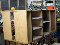
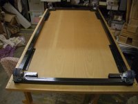
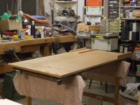
The top and bottom are made of 2 large drawing desks I salvaged from and architects office some weeks before. The sides are made up of anything I could find in the workshop, old ply, chipboard and MDF. Here the top upside down taped up for varnishing, with the cut out for the saw garage.
[attachthumb=#]
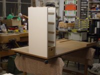
I started my drawing with the width of the DC and then added Systainers with draw runners. Then my tiny compressor and some space for draws.
The draws I recycled from old draws I found on the street, re-cut to size and simply screwed together.
[attachthumb=#]
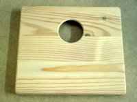
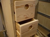
I didn't want any nobs sticking out so thought a hole would be quick and easy but I wanted to keep the dust out. So I made draw fronts with a 35mm hole
[attachthumb=#]
and the backside of which is routered with a 45 degree bit. Leaves good space for a finger tip. The fronts were 16mm.
[attachthumb=#]
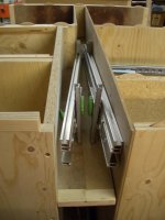
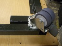
In my drawing I could see if I put my systaines back to back on their 35 cm draw shelves I had a 7 cm gap down the middle where I could safely store my rails and guides.
[attachthumb=#]
There was a set back that I couldn't get the fence rail with its big nob in to the 7cm space I needed a minimum of 10cm when the rail was tipped about 20 degrees. I didn't want to have to take it apart every time I want it quickly out of the way.
[attachthumb=#]
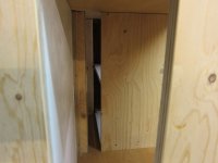
So I narrowed part of the space at the front to 30 cm making room for the angle head of the fence rail, this space then became the area for the saw garage and shelf for other tools, drills etc.
[attachthumb=#]
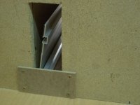
I miss calculated here and forgot the thickness of the wall so I later had to cut a hole to make the rails fit. It now helps to improve the air circulation.
[attachthumb=#]
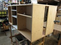
So on the back side I have the opening for the DC with the hose coming out then 2 stacks of systaines and rest of the length taken up by 5 small draws for little bits and pieces, clamps, spanners etc.
[attachthumb=#]
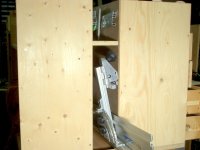
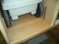
On the front side I have the back of the DC, which I fixed to stop it rolling back and here I noticed there was just enough space to put a Sys 1 standing on its edge and still have air flow. More stuff out the way.
[attachthumb=#]
[attachthumb=#]
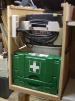
Next to that a stack of systainers and then a slopping shelf and saw garage and under that an area for my compressor.
[attachthumb=#]
This is as far as my photos go so far. I will make some more pictures and then show how my MFT Support System is developing. I'm at the painting stage at the mo so I won't bore you with lots of white painted wood laying around. More when I get it all back together.
The paint job was inspired by Jonny round boy, with his tip to use cheep white emulsion paint as an undercoat and then cover that with a water based clear varnish. It's going on easily.
Then as I had it set up in the workshop I was disappointed that it took up a lot of space but without decent storage underneath due to sloping angle of the legs. Every time I wanted to move it a bit to one side I had to move the systainers under it.
So I followed a few threads on in the FOG on improvements to MFT and was so impressed by what I saw I decided to build my own.
I took a lot of inspiration from Black Flag, mparka, and Steve Rowe's designs. I was also looking for somewhere to store my Parallel guides which stand in the corner in their box.
Thanks to Idefixes design I decided to also make space for the compressor and DC and add a saw garage and many thanks to Qwas for his 10 MFT mods. Another important feature for me was I wanted to safely store the Saw rail and Fence guide that come with the table.
[attachthumb=#]
So the length of my MFT Support System was determined by measuring the width of the CTL 36 and the length of the Saw rails, this came to around 150cm . The width was fixed by the MFT 77cm, so I can clamp work vertically on all 3 sides.
[attachthumb=#]
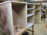
I then spent a lot of time pushing lines around on paper to figure out how I could get as much under the table top as possible. The height was an issue till I let go if the idea to keep it the same hight as the MFT (90cm) with its legs down. This then gave me room to get a Sys 1,2 and 3 plus the draw mechanism under the the top. The distance between the top and the bottom is now 66 cm. For the systainers I thought I would go the whole hog and buy full extension draw runners and found some on e-bay for 3,30 euros a pair for a 30kg load.
[attachthumb=#]
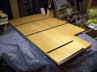
The top and bottom are made of 2 large drawing desks I salvaged from and architects office some weeks before. The sides are made up of anything I could find in the workshop, old ply, chipboard and MDF. Here the top upside down taped up for varnishing, with the cut out for the saw garage.
[attachthumb=#]
I started my drawing with the width of the DC and then added Systainers with draw runners. Then my tiny compressor and some space for draws.
The draws I recycled from old draws I found on the street, re-cut to size and simply screwed together.
[attachthumb=#]
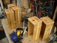
I didn't want any nobs sticking out so thought a hole would be quick and easy but I wanted to keep the dust out. So I made draw fronts with a 35mm hole
[attachthumb=#]
and the backside of which is routered with a 45 degree bit. Leaves good space for a finger tip. The fronts were 16mm.
[attachthumb=#]
In my drawing I could see if I put my systaines back to back on their 35 cm draw shelves I had a 7 cm gap down the middle where I could safely store my rails and guides.
[attachthumb=#]
There was a set back that I couldn't get the fence rail with its big nob in to the 7cm space I needed a minimum of 10cm when the rail was tipped about 20 degrees. I didn't want to have to take it apart every time I want it quickly out of the way.
[attachthumb=#]
So I narrowed part of the space at the front to 30 cm making room for the angle head of the fence rail, this space then became the area for the saw garage and shelf for other tools, drills etc.
[attachthumb=#]
I miss calculated here and forgot the thickness of the wall so I later had to cut a hole to make the rails fit. It now helps to improve the air circulation.
[attachthumb=#]
So on the back side I have the opening for the DC with the hose coming out then 2 stacks of systaines and rest of the length taken up by 5 small draws for little bits and pieces, clamps, spanners etc.
[attachthumb=#]
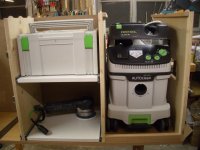
On the front side I have the back of the DC, which I fixed to stop it rolling back and here I noticed there was just enough space to put a Sys 1 standing on its edge and still have air flow. More stuff out the way.
[attachthumb=#]
[attachthumb=#]
Next to that a stack of systainers and then a slopping shelf and saw garage and under that an area for my compressor.
[attachthumb=#]
This is as far as my photos go so far. I will make some more pictures and then show how my MFT Support System is developing. I'm at the painting stage at the mo so I won't bore you with lots of white painted wood laying around. More when I get it all back together.
The paint job was inspired by Jonny round boy, with his tip to use cheep white emulsion paint as an undercoat and then cover that with a water based clear varnish. It's going on easily.
")