Bugsysiegals
Member
- Joined
- Mar 19, 2016
- Messages
- 893
Alright, this is the moment we've been waiting for ... Daniel Larusao's going to fight?!?!
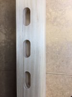
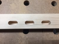
I forget the large bits were stored in the Styrofoam and not the tray. I installed the 12mm bit and did the same exercise Cheese did with results below.
View attachment 1
View attachment 2
View attachment 3
View attachment 4
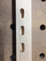
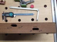
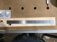
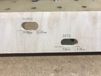
Here you can see by using a SS rule aligned with the top of the mortise, the skew/alignment I'm referring to. If you cannot see it's 15.60mm on the Left and 21.64mm on the Right.
View attachment 5
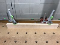
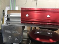
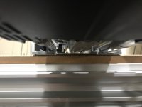
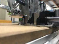
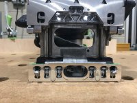
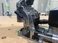
In addition, I've used clamps up front to hold the weight of the Domino, without skewing it Left/Right and allowing it to remain flat, and used a precision straight edge on the bottom of the motor mount to get a visual off the motor's plane of motion in comparison to the base plate reference plane (aligned with the top of the MFT table). As you'll see, the motor is canted which aligns perfectly with the mortises I'm making. I can't say for sure the motor housing is supposed to be perfectly parallel with its plane of motion but if it's not, I suspect it should be close and at least give the mental picture of how this motor's canted.
View attachment 6
View attachment 7
View attachment 8
View attachment 9
View attachment 10
View attachment 11
I forget the large bits were stored in the Styrofoam and not the tray. I installed the 12mm bit and did the same exercise Cheese did with results below.
View attachment 1
View attachment 2
View attachment 3
View attachment 4
Here you can see by using a SS rule aligned with the top of the mortise, the skew/alignment I'm referring to. If you cannot see it's 15.60mm on the Left and 21.64mm on the Right.
View attachment 5
In addition, I've used clamps up front to hold the weight of the Domino, without skewing it Left/Right and allowing it to remain flat, and used a precision straight edge on the bottom of the motor mount to get a visual off the motor's plane of motion in comparison to the base plate reference plane (aligned with the top of the MFT table). As you'll see, the motor is canted which aligns perfectly with the mortises I'm making. I can't say for sure the motor housing is supposed to be perfectly parallel with its plane of motion but if it's not, I suspect it should be close and at least give the mental picture of how this motor's canted.
View attachment 6
View attachment 7
View attachment 8
View attachment 9
View attachment 10
View attachment 11
Attachments
-
 thumbnail_IMG_3490.jpg290 KB · Views: 189
 -
 thumbnail_IMG_3501.jpg198.3 KB · Views: 204
 -
 thumbnail_IMG_3500.jpg184.6 KB · Views: 217
 -
 thumbnail_IMG_3499.jpg204.2 KB · Views: 225
 -
 thumbnail_IMG_3498.jpg155.5 KB · Views: 209
 -
 thumbnail_IMG_3497.jpg204.9 KB · Views: 174
 -
 thumbnail_IMG_3496.jpg179.3 KB · Views: 198
 -
 thumbnail_IMG_3495.jpg283.8 KB · Views: 323
 -
 thumbnail_IMG_3493.jpg287.3 KB · Views: 380
 -
 thumbnail_IMG_3492.jpg263.3 KB · Views: 244
 -
 thumbnail_IMG_3491.jpg227.8 KB · Views: 231