plug and playhttps://www.blocklayer.com/kerf-spacing.aspx
You are using an out of date browser. It may not display this or other websites correctly.
You should upgrade or use an alternative browser.
You should upgrade or use an alternative browser.
Non-standard use of a track saw
- Thread starter Crazyraceguy
- Start date
Cheese
Member
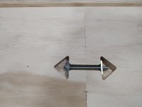
Those arrows interest me...they almost look like they're routed into the surface. Are they just spray painted on with a template and what purpose do they serve?
Vondawg
Member
Looks like end to end threaded fasteners
Cheese
Member
Vondawg said:Looks like end to end threaded fasteners
Thanks for that Vondawg... [smile]...now I get it, no wonder they looked like they were routed into the surface...Duh.
4nthony
Member
I love seeing in-process photos. It's amazing how much you can learn by simply observing what others build. Great work! [cool]
Are the "arrows" and fasteners similar to these? Would love to see a close-up.
I used these ZipBolts on a recent L-desk and they were great for keeping the two sections snug.

Cheese said:Vondawg said:Looks like end to end threaded fasteners
Thanks for that Vondawg... [smile]...now I get it, no wonder they looked like they were routed into the surface...Duh.
Are the "arrows" and fasteners similar to these? Would love to see a close-up.
I used these ZipBolts on a recent L-desk and they were great for keeping the two sections snug.
- Joined
- Oct 16, 2015
- Messages
- 5,791
Packard said:I'm curious about the math.
The depth of cut is easy enough to figure out.
The width of the cut is fixed, so no math.
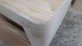
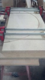
The distance between cuts needs to be calculated so that the bend is smooth and not a series of flats with a "hinge" of veneer.
Can you tell us how you did the calculations?
If I did it, I would have to make a dozen samples before I would get it right.
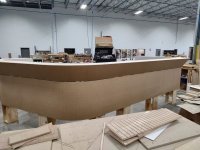
It has just been a trail and error process over time. We have several spacings programmed into the beam saw, based on bend radius. This keeps the cuts to a minimum on larger radius bends. The more cuts and "softer" the piece is, the harder they are to handle. Once the sheet is attached, it is plenty strong, but loose flopping around, not so much.
Since these were done on a cone, thus tapered, it was purely a guess. There is a bit of a balancing act involved. Not enough cuts, you get a stop sign or the kerfs bind before you reach your desired radius.
Too many cuts means it is weaker than it could be and takes too much time. The real key is the stud spacing and adequate support.
These are not "perfect", which is when the kerfs close exactly when the bend radius is where you need it to be, but they don't need to be.
- Joined
- Oct 16, 2015
- Messages
- 5,791
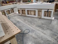
Gregor said:They use tiny monitors [blink]Crazyraceguy said:The rectangular holes will be pockets for monitors, so they sit lower than the regular top height.
Apart from that: nice execution.
The opening is 25" wide. The whole idea is that the monitors do not stick up above the line of the transaction top. It's a medical facility, they aren't graphics designers....lol
- Joined
- Oct 16, 2015
- Messages
- 5,791
Cheese said:Those arrows interest me...they almost look like they're routed into the surface. Are they just spray painted on with a template and what purpose do they serve?
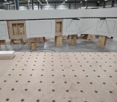
They are routed into the surface. It is a pocket to accept a "Tite-Joint" bolt, usually called a Dog Bone.
It's a simple 1/4-20 bolt with a rectangular washer and nut. We use them for countertop field joints, so they are always around and commonly used for everything. The places were they are in this top plate are permanent "shop joints". On narrow boards, I use a couple of 6mm Dominos and a pocket screw to pull them together. With wider plates like these (12.5") they get the bigger bolt.
The arrow shape is so that you can put the bolt in either way.
- Joined
- Oct 16, 2015
- Messages
- 5,791
tsmi243 said:Super cool 8)
What kind of accuracy is normal on something that big? I feel pretty good about my kitchen cabinets being within ~2mm over a 10' run, but even getting THAT takes a lot of time (not a pro).
That is kind of hard to say. "It depends", which is the worst answer ever. Some things are very strict and others just aren't.
Not long ago, I made a huge "soffit" kind of thing that was well over 40 feet long, multiple pieces. It had to fit into a wall to wall trapped situation and be dead on accurate. Assembled on the shop floor and laser measured with the same tool that was used on-site to the location where it was to be installed, it was under 1/16" short.
Other times where something sits out on its own, I won't bother to cut it undersized to compensate for the thickness of the veneer or laminate. It doesn't have to "fit" in anywhere, so it doesn't matter. No one is going to measure it and complain because it is 48 1/8th, when the drawing called for 48.
Things like squareness and straightness are far more important.
- Joined
- Oct 16, 2015
- Messages
- 5,791
4nthony said:I love seeing in-process photos. It's amazing how much you can learn by simply observing what others build. Great work! [cool]
Cheese said:Vondawg said:Looks like end to end threaded fasteners
Thanks for that Vondawg... [smile]...now I get it, no wonder they looked like they were routed into the surface...Duh.
Are the "arrows" and fasteners similar to these? Would love to see a close-up.
I used these ZipBolts on a recent L-desk and they were great for keeping the two sections snug.
Very similar, exactly the same concept, those are considerably more expensive though. When you use as many as we do, it adds up quick.
- Joined
- Oct 16, 2015
- Messages
- 5,791
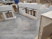
It is done, apart, and down on the floor. I thought I took a pic yesterday when the plywood sub-tops were on, but apparently not? I have one of the inside with the access panels on, then with the outside covering, and then broken apart for shipping.
Attachments
Packard
Member
Crazyraceguy said:Packard said:I'm curious about the math.
The depth of cut is easy enough to figure out.
The width of the cut is fixed, so no math.
The distance between cuts needs to be calculated so that the bend is smooth and not a series of flats with a "hinge" of veneer.
Can you tell us how you did the calculations?
If I did it, I would have to make a dozen samples before I would get it right.
It has just been a trail and error process over time. We have several spacings programmed into the beam saw, based on bend radius. This keeps the cuts to a minimum on larger radius bends. The more cuts and "softer" the piece is, the harder they are to handle. Once the sheet is attached, it is plenty strong, but loose flopping around, not so much.
Since these were done on a cone, thus tapered, it was purely a guess. There is a bit of a balancing act involved. Not enough cuts, you get a stop sign or the kerfs bind before you reach your desired radius.
Too many cuts means it is weaker than it could be and takes too much time. The real key is the stud spacing and adequate support.
These are not "perfect", which is when the kerfs close exactly when the bend radius is where you need it to be, but they don't need to be.
Thanks for that. The few magazine articles I have seen on this show the kerfs closing perfectly with the bend. But no one seems to show the math on that. So maybe there is no math. Just a bunch of "experts" throwing spaghetti against the wall to see what sticks.
Cheese
Member
Packard said:Thanks for that. The few magazine articles I have seen on this show the kerfs closing perfectly with the bend. But no one seems to show the math on that. So maybe there is no math. Just a bunch of "experts" throwing spaghetti against the wall to see what sticks.
See guybo post #21, it's an easy to use calculator.
Packard
Member
Cheese said:Packard said:Thanks for that. The few magazine articles I have seen on this show the kerfs closing perfectly with the bend. But no one seems to show the math on that. So maybe there is no math. Just a bunch of "experts" throwing spaghetti against the wall to see what sticks.
See guybo post #21, it's an easy to use calculator.
Thanks. I copied that site to my phone. I may need it in the future. I've only ever seen bending done with plywood. Will this work as well with solid wood? Any species to avoid?
Packard
Member
So, still I will have to experiment on samples. Thanks. I have an idea for a project where this might work.
- Joined
- Oct 16, 2015
- Messages
- 5,791
Closer view of the Tite-joint bolt as requested.
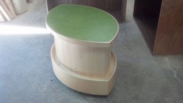
Also an old pic of a much tighter bend from several years ago.
I have never tried kerf bending for solid wood, mostly because of the look. It seems like there would be no need for solid wood if you couldn't see the sides? It could just be ply?
I have done both bent-lamination and steam bending with good results. The only pics I can find are from a big library job from a few years ago. There were several of these tables, I think 6? so it took some time, but I worked them in while doing other projects. It took a couple of tries to get the form right, because of "spring-back". I had to make the form quite a bit tighter than the actual parts needed to be. Steam bending has more spring-back than lamination bending. I'm sure that it is species dependent in some way? This was done with maple. I would steam the parts for a few hours, clamp up 2 sets at a time and let them sit until the next afternoon, when the next ones were ready.
The main thing I have experienced with steam bending is that the outside of the form is just as important, maybe more, than the inside. You need that compression/pressure to keep the parts from cracking.
Lamination bending is mostly about the thickness of the pieces. Tighter bends need thinner layers, but more layers means more work that you don't need to waste time with, if the bend doesn't require it.
The glue plays a part in it too. Some types cure harder/stiffer, that has an effect on spring-back.
The end use of the parts makes a difference too. If the bent piece is a bit of trim that will get attached to something else, the spring-back may not be as important. It's a balance, kind of like the kerf method.
Attachments
4nthony
Member
Crazyraceguy said:Closer view of the Tite-joint bolt as requested.
Nice. A much simpler design for sure. I was curious how you tightened them but now that I see there's no threads near the head, it makes perfect sense. And a great way to cut down on costs when needing to use them in large quantities.
Similar threads
- Replies
- 15
- Views
- 440
- Replies
- 58
- Views
- 3K
- Replies
- 14
- Views
- 1K