I have had my Nova Voyager for nearly a couple of years, but funnily enough I am only just now getting round to making a new table and cabinet for it - I will do a write up in due course, including my geared rise and fall operated by cordless drill.
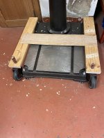
Anyway, mobility is essential in my workshop and I pondered long over this - I didn’t want outriding wheels and brackets as they are a hazard and not least because I want to be able to wheel the cabinet over the base (in one of the pictures below, you can see me playing around with some scrap to work out this arrangement).
My mobility solution is some heavy duty rollers and static feet that can be wound down to lift the base and rollers off the ground and level the whole machine.
Sorry I don’t have any decent pictures yet (and the Voyager is not that simple to just turn over for an underneath shot!)
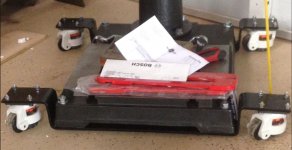
[attachimg=1]
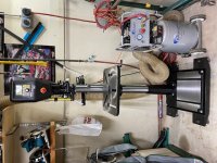
This shows the overall arrangement and a mock-up of how the cabinet will slide into position (fixed wheels at the back of the cabinet).
[attachimg=2]
[attachimg=3]
[attachimg=4]
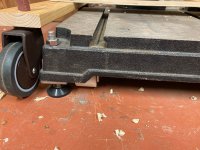
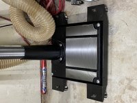
The rollers are an inline pair in each corner set into little “trucks” fabricated from some 50mm sq tube and spindles with retaining circlips. These are screwed to wooden packers set and glued into the recesses in the webbed cast iron base (I was going to weld the “trucks” together into an under frame, but decided this was easier in the end and the weight is dispersed across a decent area).
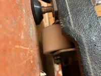
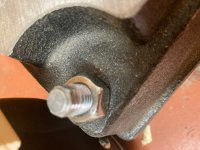
The feet are heavy duty machine feet with M12 threaded legs - these are threaded into some threaded weld nuts that I welded to the (5mm thick) corner plates under each corner - the corner plates sit under the rim of the base and are screwed into wooden packers glued into each corner (I was unsure whether the corner hole positions in the base, that are evidently intended for bolting down, would take the weight or any stresses that may result from fixing the feet just to these points (so my arrangement transfers all the weight through the rim of the base in the same way as if it is stood directly on the ground - this may have been OTT, I don’t know, but better safe than sorry.)
I filed a hex on the top of the threaded legs (came out at 3/8”) and this enables the feet to be raised and lowered with a spanner and locked off with the locknut. I had originally intended to just keep the machine sitting on the rollers and make some little chocks to keep it from moving, but I wasn’t happy with this in the end so went with the proper feet, which also means it can be properly levelled with a 360degree bubble level.
The rollers move the whole machine really smoothly (in fact the slightest gradient will move it!) and it seems easy enough to go round corners, a point I was unsure of given that the rollers are fixed in line.
As I say, when this is all finally finished I will follow up with full details, probably on this enormous thread.
Cheers