smorgasbord
Member
mino said:From the TLL-90S specs:
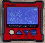
1) High accuracy ± 0.005° and 0.001° high resolution;
That is how a proper metrological spec should look. This one seem to be the real deal.
Depending on which model/age of Wixey he's testing, the current unit's spec is:
http://www.wixey.com/anglegauge/index.html#wr300type2Specifications
Range: +/- 180 degrees
Resolution: 0.1 degrees
Accuracy: +/- 0.2 degrees
Repeatability : +/- 0.1 degrees
So that would seem to conform to your expectations.
mino said:Unfortunately those "tests" are just random chance. Claiming a digital scale with a 0.1° resolution to be "spot on" down to 0.1° accuracy is just amateurish at best, misleading at worst. What they actually checked is the Wixie one is indeed within the +/- 0.2° range that it can display. And that even ignores if they used a calibrated reference (most likely not ..).
Wixey itself only claims +/-0.2º accuracy, so his tests, while not against traceable units, does seem to confirm that. I would expect that most surface plates, sine bars, and gage blocks, if not the cheapest junk available and properly cared for, would be far more accurate than the Wixey unit being tested, and so would give a reasonable estimate of its accuracy, or lack thereof.
The $45 unit I just purchased, which hasn't arrived yet, is specced at an accuracy of +/-0.05º and resolution of +/-0.01º. I don't understand how it could be different enough to be 4X more accurate than the $20 cheapies at double the price, but for this money I'm interested in it just for the convenience for non-super-critical blade angle and jointer fence settings as well an curiosity.