- Joined
- Nov 21, 2015
- Messages
- 614
Jruks said:Mike Goetzke said:This is strange - following this thread seems TSO supplied systems haven't had issues but from Axminister directly they have. Is there extra effort or additional QC steps taken to assure TSO gets good product?
I can’t answer this personally. Would seem odd if that was the case though..
[member=70391]Jruks[/member] – in response to your question about any “extra effort” TSO puts into the AXMINSTER products we ship: normally we do not open the products we receive from AXMINSTER before shipping them to our customers. The exception involves the Parf Guide (original) and Parf Guide Mark 2 where, until recently, we added a Clamping Collar to the shipment.
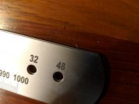
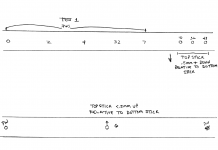
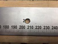
We have received one (1) report of questionable PGS Mark 2 Parf Stick rule accuracy and we are subjecting that part to lab analysis. In other words, TSO has not seen any Parf Stick difficulties rising to the level of even 1% of Mark 2 shipments.
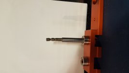
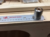
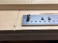
The intentional very tight fits of the Parf Guide System do result in joining parts requiring some manual pushing to go together the first time or two until the mating surfaces have knocked down any interfering high spots.
We have seen a missing part report here or there but nothing pointing to broader quality issues. After all, a customer problem creates an equal or greater TSO internal workload. So, we are doubly vigilant about all aspects of quality. Reports on the FOG also get our attention and send us checking our own performance.
Hans
")