I’m just making my first Parf bench top. It’s in valchromat, and I’ve spent a while making sure it’s flat.
Firstly I noticed that the 3 mm guide doesn’t seem to fit in the Parf guide very tightly, it can wobble a bit.
I made my first row of 10, then a right angle at each end. I noticed that once I had made the 6,8,10 triangle that the Parf guide could be could be wobbled some fraction of a Millimeter. I tried to hold everything right and drilled 3mm holes. I then put the 10th 3mm holes on each of these columns. Then I put the Parf guide between these two 10th holes and found that they didn’t line up perfectly.
Clamping things doesn’t seem to make a difference.
I tried uploading a video of 3mm guide wiggle, and one of triangle wiggle but I dont think vids are allowed.
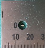
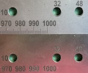
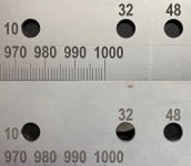
So I just uploaded a photo of how much the hole is off by.
Is this normal?
Thanks
Firstly I noticed that the 3 mm guide doesn’t seem to fit in the Parf guide very tightly, it can wobble a bit.
I made my first row of 10, then a right angle at each end. I noticed that once I had made the 6,8,10 triangle that the Parf guide could be could be wobbled some fraction of a Millimeter. I tried to hold everything right and drilled 3mm holes. I then put the 10th 3mm holes on each of these columns. Then I put the Parf guide between these two 10th holes and found that they didn’t line up perfectly.
Clamping things doesn’t seem to make a difference.
I tried uploading a video of 3mm guide wiggle, and one of triangle wiggle but I dont think vids are allowed.
So I just uploaded a photo of how much the hole is off by.
Is this normal?
Thanks