Plans for MFT3 / Sysport cabinet

Kodi Crescent

Member
Joined
Aug 6, 2010
Messages
791
Hi.  I'm getting ready to make some sort plans for a sysport-like cabinet that my MFT/3 will sit on.  My plan is to have a rolling MFT that I can wheel around that will contain space for some systainers and a CT-22.  Surely someone here has done this before.

Does anyone have any plans or pictures of ones that you've built?

Thanks!
 
Kodi Crescent said:
Hi.  I'm getting ready to make some sort plans for a sysport-like cabinet that my MFT/3 will sit on.  My plan is to have a rolling MFT that I can wheel around that will contain space for some systainers and a CT-22.  Surely someone here has done this before.

Does anyone have any plans or pictures of ones that you've built?

Thanks!

Here is what I did (combined rolling MFT + CMS)
http://festoolownersgroup.com/festool-jigs-tool-enhancements/sysport-cms-mft-(work-in-progress)/
 
I've had some down time this week, so I built my own version of a rolling MFT/3-Sysport using 18mm baltic birch plywood.  The criteria were that it had to be built 100% on metric system (my first), it had to hold an MFT/3 (with legs folded) at normal height so it would line up with my other MFT/3 sitting on its own legs, it had to have the same footprint as an MFT/3, interior partitions had to be line-bored to accept drawer glides and/or shelves, and it had to be assembled using dominoes (I also used pocket screws to keep things together as the adhesive set up).  I used 101.6mm locking casters from Woodcraft which are 130mm high including hardware, and sized all the component parts from there to achieve the goals.  It's still a work in progress; I still have to acquire some Accuride glides and make the pull-out shelves.  The center sections are likely to have drawers in which I can store boxes of abrasives for my various Festool sanders.  In any case, it rolls around quite well and the locking casters hold it in place quite well.  As you can see, I nailed the height just right.  There are four 100mm x 50mm x 12mm pads glued and brad-nailed to the top as alignment blocks to keep the MFT/3 from slipping off during material manipulation.  They are there for alignment only.  The MFT/3 actually sits on its own pads.  If any FOGgers are interested in the cut sheets which have dimensions, I can send them as a PDF file.  

And yes, I know there's a nut missing on one of the caster pads.  There was apparently a 1/4" nut in the box of 5/16" elastic nuts, so there's another trip to Lowe's.  

Edit, 12/23/13:  I did some re-thinking today of how I did the system holes in my Sysport, and have modified the narrative PDF file to reflect the re-think.  Both the cutsheet and the narrative document are now attached to this message for your ease in downloading.  

[smile]


Attachments

Damn fine job, sir!

I would be tempted to shift the fence and guide rail to the other MFT top to give yourself really good outfeed support.
 
Richard Leon said:
Damn fine job, sir!

I would be tempted to shift the fence and guide rail to the other MFT top to give yourself really good outfeed support.

Thank you kindly, sir.  I considered that, and may just reverse the order of MFT/3s in the shop to do that.  The shop is in quite a bit of disarray at the moment as I reconstruct things, and like the ability to use the new sysport as a roll-around close to the door.  I still have the obstructions of two Lally columns in the shop to contend with, and if I do reverse the order of the tables, one will be right smack in the way of the rail.  Much yet to be done in any case. 

[smile]
 
Thanks!  That's very similar to what I plan on doing.  I'm considering the aluminum version as well.  That may be outside the budget though.
 
Just as a follow-up, here's a photo of my version of the Sysport with the shelves mounted on glides.  I used dominoes to keep the systainers from sliding off to the front, and a simple cleat on the rear of the shelves to keep the systainers from sliding off to the rear, although I'll likely replace the cleats with dominoes in the near future.  Each of the large compartments will hold a Sys4 and a Sys2 or three Sys2s.  The space under the MFT/3 turns out to be a good place to stash the parallel guides, too. 

[smile]

 
As a fairly new member here, I am still working my way through old threads to educate myself and benefit from the wisdom of others. Since it has been over 2 years since you built this, I am wondering what you have learned in that time and if you'd do anything differently?
 
wow said:
As a fairly new member here, I am still working my way through old threads to educate myself and benefit from the wisdom of others. Since it has been over 2 years since you built this, I am wondering what you have learned in that time and if you'd do anything differently?

Wayne, I apologize for not seeing your post (below) sooner.  There are a few things I'd do differently with 20/20 hindsight. 
  • First, I'd use the LR 32 to line bore the system holes into which I screw the drawer glides (I didn't have the LR 32 when I made this.)  I'd also use a horizontal pattern that reflected the actual spacing of system holes in the glides.  This was not clear thinking on my part when I built it to not be aware of that spacing and adhere to it.  With the LR 32 and parallel guides, it would be a piece of cake to do it right. 
  • Second, I'd use QWAS Dogs in 20mm holes (or something like them) to locate the corners of the MFT on the top of the Sysport rather than the glued-on blocks. 
  • Third, I'd edge-band the exposed edges to make them a good bit neater.  This would entail reducing certain dimensions slightly to compensate for the additional thickness of the edge banding. 
  • Fourth, I'd eliminate the narrow center section on each side and move the columns adjacent to each other, making it possible to place drawers on one end, much as SPrior (Steve) did.  I really like that idea. 
  • Fifth, I'd not store the parallel guides under the MFT.  They make it a real pain to do post-work clean-up. 
  • Sixth, I'd spray paint the entire assembly in a gray that closely matches the Festool gray, or alternatively, use Osmo Poly-X on the Sysport as well as the MFT tops to be consistent.  Yeah, I know, it's a bit anal... 
  • Seventh, I'd consider making a built-in port in which to park the CT 22, keeping the boom arm much closer to the Sysport, and allowing room for proper ventilation.  This would eliminate some of the drawers, I know.  Someone else on the FOG did something like this and I like the concept. 
  • Eighth, I'd mount a power strip to one end. 
If anything else comes to mind, I'll prattle on about that when it strikes me. 
 
Your first and third points are changes I made between ver 1 and 2 of my design so I totally agree.

For your second point I'll say that I rarely (almost never) take the MFT off the cabinet so it shouldn't matter much, but I went with a circle of dowel screwed into the corners instead of a glued block just in case.  Now that you mention the QWas dog idea though...  After I finished this I got a 3D printer and as a test printed some dogs, now sometime when I get bored I'll print up 4 of them that fit a MFT hole and have the same diameter as the dowels, drill the holes and swap them in.

The drawers on the end are REALLY nice.  My only nit was that if they were just slightly taller my Syslite would fit in them while in their case without dragging across the top - works the way it is.  I have a space for my Seneca parallel guides (I sold my Festool guides and bought these) under the drawers so I don't have the cleanup issue.

While I should have done a poly finish on my cabinet, I'm real lazy about finishes.
 
Steve, I also almost never take the MFT off the Sysport, except when I need additional assembly space.  The blocks I used originally work perfectly for holding on the MFT, but I think that they get in the way sometimes when the MFT is not atop the Sysport.  The QWAS dogs might alleviate that issue.  I'd be interested in knowing if your 3D printed versions work well.  You might be able to make the larger diameter tops a bit lower to match the height of the gray plastic pads on the MFT. 

 
Sparktrician,

Just sent you a PM - I think.  If you didn't get it let me know.
 
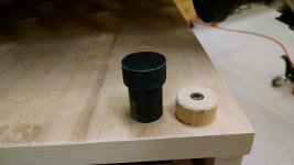
Because it was just that easy I designed and printed a sample dog on the 3D printer.  It's made of ABS plastic with a 50% infill and the small end with a 19.95mm diameter fits like a glove in a MFT hole and the top diameter of 24.5mm matches the dowel that currently locks the MFT in place.  It's strong enough to use for clamping, but of course not calibrated like a real Qwas dog.  I should have no problem drilling holes centered on the screw hole and then I can drop the dog in the place of the dowel.  Just have to print 3 more just like it.
 

Attachments

  • 2014-10-23 21.26.57.jpg
    2014-10-23 21.26.57.jpg
    214.2 KB · Views: 1,044
sprior said:
I should have no problem drilling holes centered on the screw hole and then I can drop the dog in the place of the dowel.  Just have to print 3 more just like it.

How about printing the dogs with the holes already missing from the design? Should save on plastic and be more precise? Just an idea though, as I have no experience with 3D printing.
 
The screw hole I was referring to is in the top of the cabinet.  If you look at the round piece of dowel on the right you can see it is screwed into the top.  What I'm talking about is drilling a 20mm hole through the top centered on the existing screw hole once that dowel is removed.  Then I can slip the plastic dog into that hole and it will have the same dimension and location on the table as the piece of dowel it will replace, but it will simply pull out of the hole when desired.
 
Sparktrician said:
wow said:
As a fairly new member here, I am still working my way through old threads to educate myself and benefit from the wisdom of others. Since it has been over 2 years since you built this, I am wondering what you have learned in that time and if you'd do anything differently?

Wayne, I apologize for not seeing your post (below) sooner.  There are a few things I'd do differently with 20/20 hindsight. 
  • First, I'd use the LR 32 to line bore the system holes into which I screw the drawer glides (I didn't have the LR 32 when I made this.)  I'd also use a horizontal pattern that reflected the actual spacing of system holes in the glides.  This was not clear thinking on my part when I built it to not be aware of that spacing and adhere to it.  With the LR 32 and parallel guides, it would be a piece of cake to do it right. 
  • Second, I'd use QWAS Dogs in 20mm holes (or something like them) to locate the corners of the MFT on the top of the Sysport rather than the glued-on blocks. 
  • Third, I'd edge-band the exposed edges to make them a good bit neater.  This would entail reducing certain dimensions slightly to compensate for the additional thickness of the edge banding. 
  • Fourth, I'd eliminate the narrow center section on each side and move the columns adjacent to each other, making it possible to place drawers on one end, much as SPrior (Steve) did.  I really like that idea. 
  • Fifth, I'd not store the parallel guides under the MFT.  They make it a real pain to do post-work clean-up. 
  • Sixth, I'd spray paint the entire assembly in a gray that closely matches the Festool gray, or alternatively, use Osmo Poly-X on the Sysport as well as the MFT tops to be consistent.  Yeah, I know, it's a bit anal... 
  • Seventh, I'd consider making a built-in port in which to park the CT 22, keeping the boom arm much closer to the Sysport, and allowing room for proper ventilation.  This would eliminate some of the drawers, I know.  Someone else on the FOG did something like this and I like the concept. 
  • Eighth, I'd mount a power strip to one end. 
If anything else comes to mind, I'll prattle on about that when it strikes me.

Great synopsis - thanks! I have yet to start building my MFT or Sys Cart, so I really appreciate your insights.
 
I think Sparktrician has made a Sysport cabinet that I will emulate when I reach the stage where I need one. I like that he uses Two MFT/3's so he can take it of the Sys port to make extra assembley space, the modular aspect is very appealling!!

Thanks for sharing!
 
Back
Top