Peter Parfitt said:
wow said:
jonny round boy said:
wow said:
Can you just use a pattern clamped to the top of the boards just like you have then laid out, then run a router down the joint between the two pieces? Any irregularities will be repeated on both pieces and cancel each other out, making a perfect joint.
Wayne,
That method works when doing straight joints, but won't work on a curve. The two radii will never come out the same, they will always differ by the diameter of the router bit.
Are you telling me that my spacial reasoning is flawed? It's not, you know. My procedure will work fine...
...you just need to use a small enough bit! 1mm bit = no more than 1mm error.
[embarassed] [big grin]
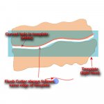
It will work. You need a pattern piece that has a smooth curve as close as you can get to the line of the two edges as they are now running through the centre of the pattern. After you create the pattern it should look like a slab of MDF with a channel running through near the centre. The pattern has to be longer than the boards you have so that the two halves of the pattern stay together.
You will use the same edge of the grove for all of the cutting and this guarantees the accuracy.
You then use that pattern, first on one piece and then the other, using a flush cutter with the ball bearing running on the pattern piece.
Peter
No Peter, it won't work. Not on a curve.
Let's say you make a curved template with a radius of 2000mm. If you follow that template with a bearing-guided trimming bit, you'll get the first piece with a radius of 2000mm. All ok so far.
Now, if you then use that same 2000mm template to cut the
opposite side of the joint, it will have a radius of
2000mm plus or minus the diameter of the router bit (depending on whether the edge of the template you use is concave or convex).
Obviously the longer the arc the more that difference comes into play - on a very short arc you might get away with it & be able to clamp it up, but on a fairly long arc like the one the OP pictured you're going to end up with a gap of several mm at each end when the pieces are pushed together.