I am building a workbench and in order to save space in my one-car workshop, I want to get rid of the Bosch table top router table and instead, want to incorporate the router (Bosch 1617) into the workbench. Was thinking of a 3/4" MDF top in a maple frame. Most of the surface will have the 20mm holes (as in the MFT), with a router lift added on one end. For the lift, I am considering the Woodpeckers Precision Router Lift V2 or the Jessem Mast-R-Lift II. So the plan is to simply cut out the top to allow the lift face plate to fit in. Is there any problem with this plan? Will I run into difficulties when trying to secure the lift into the top? Has anyone done this, or do you have any suggestions? Many thanks.
You are using an out of date browser. It may not display this or other websites correctly.
You should upgrade or use an alternative browser.
You should upgrade or use an alternative browser.
Router lift in home made table top
- Thread starter koenbro
- Start date
So I started building my homemade router table using a 2'x4' MDF piece on a 3/4" ply cabinet. This rolling cabinet will also fit my planer, 25x25 cm CNC and Ridgid oscillating sander. Saving space in my one-car shop and keeping to a budget [wink]


Sent from my Pixel XL using Tapatalk
Sent from my Pixel XL using Tapatalk
3PedalMINI
Member
- Joined
- Nov 30, 2012
- Messages
- 492
Sweet! I went back and forth on combining things like you did. I am in the same boat you are with a small area to work in. I decided at the end of the day to dedicate a router table with a bunch of storage in it and a separate workbench with a bunch of storage in it. After laying it out over and over I realized that if I did both it would save space in the long run because of the extra storage areas!
So this looks great. Your original comment talked about MFT style holes. Have you changed up your design or have just not done that yet? I assume that would be in the top to the right of the middle verticals in the cabinet?
Also, between the lift and the router there has to be 15+ pounds hanging there and I am guessing that the distance between those verticals is what, 30-36”? With 3/4” mdf as your top are you concerned about sag? Some hard maple supports under the top and secured to the verticals might help make sure that MDF stays put. If the MDF does sag, once it does it will be a lot harder to get the top back flat again. Just thinking out loud. What do you think?
Also, between the lift and the router there has to be 15+ pounds hanging there and I am guessing that the distance between those verticals is what, 30-36”? With 3/4” mdf as your top are you concerned about sag? Some hard maple supports under the top and secured to the verticals might help make sure that MDF stays put. If the MDF does sag, once it does it will be a lot harder to get the top back flat again. Just thinking out loud. What do you think?
Yes, I almost went back and added angle iron as an option instead of the hard maple that I originally suggested.
I went down and looked at my Jessesm which is a 3/4” phenolic top that is 32” wide. It does not have any extra support underneath but it sits on a table frame that is only 26” wide and is bolted to that frame on all four sides. Between the narrower span and the phenolic sagging is not a problem.
I went down and looked at my Jessesm which is a 3/4” phenolic top that is 32” wide. It does not have any extra support underneath but it sits on a table frame that is only 26” wide and is bolted to that frame on all four sides. Between the narrower span and the phenolic sagging is not a problem.
Alanbach said:So this looks great. Your original comment talked about MFT style holes. Have you changed up your design or have just not done that yet? I assume that would be in the top to the right of the middle verticals in the cabinet?
I have changed the design of this table. Originally I wanted to make the right-half a 96mm MFT hole pattern, following
Toolify's method,
but I will put a laptop in a drawer just below the MDF surface and don't want dust to fall through the top into it (the laptop controls the CNC, and the drawer will also include the CNC's control board).
Alanbach said:Also, between the lift and the router there has to be 15+ pounds hanging there and I am guessing that the distance between those verticals is what, 30-36”? With 3/4” mdf as your top are you concerned about sag? Some hard maple supports under the top and secured to the verticals might help make sure that MDF stays put. If the MDF does sag, once it does it will be a lot harder to get the top back flat again. Just thinking out loud. What do you think?
My inexperience is showing. Agree that the span of 28" across and 24" deep could lead to sagging, but I simply did not design any support. The MDF is designed to be replaced and sits on top of a maple frame and I can lift it out, and add some maple cross-supports, and will definitely do that. I also want to add some enclosure around the router to better control dust collection (smth like this), so the cross supports will allow attaching the router enclosure. Thank you for the idea!
So I really don’t mean to pile on here but regarding the issue of additional support I would try to design new supports that are beefy and independent and well placed around the cutout as that will be the weakest area. I would not be as concerned with double use as hangers for the dust collection housing. Remember that if you use that Rockler box (link you provided) you will be adding another 16 pounds. I would be concerned with support across the width, not so much front to back based on the location of the fence, feed direction and the fact that the width is the longer span. If it was me I would probably glue and screw laminate two of my own little lam-beams out of two hard maple 1x4’s (for each one) and glue and screw through the side / center vertical support. You could make them less than 3.5” if you need to for access / clearance sake (especially in the front) where access will be more critical. Just make sure to think through all of the access issues up front because if you follow my installation advice you will have a heck of a time getting them back out of there. You will have to find a balance between maximum support as close the cutout as possible and moving forward and back to create ample access around the router and the dust collection.
If you have a Kreg jig you could drill some pocket holes in the beam so that you could run some screws into the top from the bottom without hurting your removable top concept. This will create a unitized approach will will hinder future movement even more.
I hope this helps.
If you have a Kreg jig you could drill some pocket holes in the beam so that you could run some screws into the top from the bottom without hurting your removable top concept. This will create a unitized approach will will hinder future movement even more.
I hope this helps.
Alanbach said:I would try to design new supports that are beefy and independent and well placed around the cutout as that will be the weakest area. [...] I hope this helps.
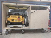
Sure thing: a week into it, the top was not flat. The weight of the planer (90 lbs) bowed down the floor plywood between the casters (~4' apart). The distortion "pulled" down the mid-wall, bowed the top maple frame and pulled the MDF into a bow, as it was screwed into the frame. That was even before accounting for the weight of the router.
So I placed another pair of casters directly under the planer so its weight is now fully supported.
[attachimg=1]
That immediately corrected most of the bowing. Then I fabricated a steel frame from 1" x 1/8" angle, placed it on top of the maple frame, and laid the MDF back onto it. Now the MDF is straight and hope it stays that way. [attachimg=2]
Attachments

Similar threads
- Replies
- 0
- Views
- 571
- Replies
- 7
- Views
- 4K
- Replies
- 22
- Views
- 4K