Richard/RMW said:
I'd differ on that, SO employs a Z axis, it's just the depth of cut isn't encoded into the file.
Where it benefits from the SO F360 plugin is various cuts are color coded when the file is made from a body, which has Z depth, then the device recognizes the color and defaults to the proper type of cut.
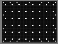
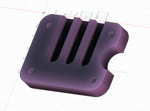
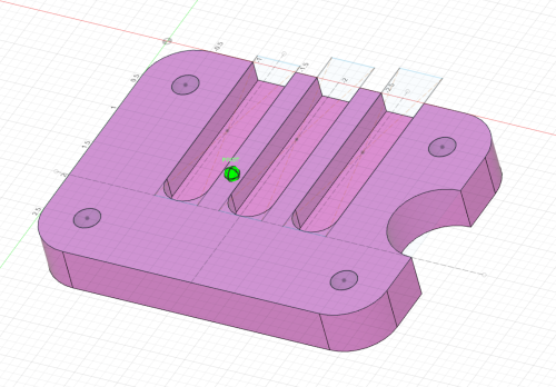
An example is this MFT style top with 20mm holes along with countersunk holes for fasteners, the color for outer profile, through holes and pockets (black/white/grey). I can pocket 20mm using a 1/2" bit with Helix, same for the 8mm through holes using a 1/4" bit, by changing the z depth of cut on the tool. This is fantastic as I don't need to guide the tool by hand, just hold it in place while it helixes.
My personal opinion is F360 is great for stuff like the MFT top. More organic shapes are not my cup of tea, but I do think a graphic design program is probably better suited.
RMW
Again though, the Z axis is not "active" in the cut. It can only plunge to the depth that you tell it and pull all of the way back out when you hit retract. It cannot "carve" like a tabletop CNC machine can.
Things like the squared corners of lettering can be done with a V-bit, where the Z axis pulls the bit up in the corners, on a tabletop CNC. Origin can't do that.
Of course that tabletop machine can't do anything on your floor or a bartop, so there are advantages/trade-offs with either.
As an example. If you need to cut the double depth pocket of a SOSS hinge, you treat it as two separate cuts. The longer shallower cut first, then back over the same place again deeper. The second pocket would be deeper, shorter and inside the first one, but this doesn't happen from within the file.
It will tell you "on screen", but it's up to you to actually set that depth.
This is what I mean by "not active". Depth (Z) is not part of the file, it must be set by you, and it cannot change during the cut. It cuts at the same depth through the entire cut, until you retract, or get too far off line. Even then it just aborts and pulls fully out. There again, you aren't likely to get the edge of your door lined up on your tabletop CNC either, but point made.
With a CNC machine, it might cut the shallow pocket first too, but it will come back around and go deeper on the next pass, depending upon the depth of both and parameters of the machine itself. That happens within the file.
You can only "Helix" in a certain range too. It only works within it's "error range", so you couldn't helix a 1" hole with a 1/4" bit. It can't move the bit "that far" away from it's centered position.