Split Top Roubo MFT with Benchcrafted, Incra and 80/20

I am mostly doing small projects.  When crosscutting narrow stock, the guide rail will tip as the saw is moved towards the cut.  The rail will flatten as the saw passes over the stock being cut.  However, i place a couple of scraps under the suspended length of the rail and this eliminates the tipping problem.  It may be that the scraps are not necessary, but i am more comfortable in using them. 

Besides, it justifies keeping all of those scraps  ::)
Tinker
 
Does anyone have thoughts on a base design? I'm going with aluminum extrusions as a sub-base. This will keep the tops co-planer. I think the aluminum running parallel with the end caps, four lengths in total would suffice. The only other thing I'm thinking is to put a T-track in the subbase attached flush to the back of the long aprons. These tracks would allow for a sliding deadman to be easily placed flush with the apron.
Sub base issues aside does anyone see an issue with attaching the legs to the aluminum sub base with angle brackets? The aluminum is 80/20 inc and their catalogue has lots of brackets for this type of application. Do I need to worry about having the legs jointed up into the top structure?  Would simply butting them to the bottom of the top slab and rigidly attaching the sub-base to both parts work? My biggest concern is making sure I am deadening mallet blows through wood and not the aluminum.
 
Sean KS said:
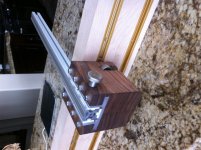
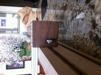
Rmw and Michael, the reason I like locking the guide to the braket is cause I use the guide with a Mirco Fence interface for routing operations, such as hardwood dadoing or sliding dovetails. This action puts a good amount of torque on the guide rail and I'd be afraid of slipping off the HAR and coming out of alignment during te routing operation. The TS 75 doesn't cause concerns in the same regard. You guys have used the pins in real time, do you think my concerns are grounded in terms of routing operations? Thanks for your thoughts!

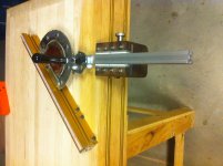
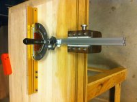
Corwin, What type of operations are you concerned about tipping occurring? In rip operations the work piece supports the guide rail so tipping can't happen then. Even in narrow rips using the incra positioner the guide rail has support. I can see certain routing operations causing worry but a piece of scrap material very simply remedies that worry. I can only guess your concerns are regarding cross cuts where the workpiece does not extend under the guide. A rare cut that I would opt for using the table saw. If I needed to do this cut with the TS 75, let's say on a very long board, once again a scrap block would support the guide from tipping. I see big advantages in having a single round contact point in the guide rail braket for ease of alignment, an issue that the festool system fails to solve with much confidence. Can you please describe what procedure your tipping concerns would pertain to if I am missing something?
Thanks for your guys help it's extremely beneficial

Sean,

For routing I think you would need to secure the rail to the pin/bracket/whatever you use. it is not a real issue with the TS for the most part and you can always use your off-hand to pull the rail into the pins/brackets while cutting. My earliest experiments with this approach used a couple simple plastic plates I cut by hand to accomplish this:

[attachthumb=#]

[attachthumb=#]

As long as the pin actually touches the rail rather than the plastic clip accuracy is maintained.

And Corwin is right-on that the rail will tip when cutting narrower stock, but as Wayne noted you can prevent this by supporting the ends with scraps of the same thickness stock you are cutting:

[attachthumb=#]

Further to Corwin's point, there are trade-offs using this approach instead of, for example, Festool's own stock MFT hardware. In the case of DIY MFT-type benches the Festool hardware is probably not suitable so you need an alternate solution. In my case, I just did not like the height adjustment on the stock hardware nor did I like having a rail always mounted to my MFT so I chose to go this route and deal with the rail tipping as part of the trade-off.

Looking forward to seeing some more photos as this takes shape.

RMW
 
How about a pre-built bracket? 80/20 has linear bearings as well, they come with a brake. The idea is to attach the bearing to the bench apron t track, then use a short length of extrusion to adjust the height of the guide rail. The extrusion does the same thing as RMW's guide pin. The extrusion can be locked to the guide rail using a concealed right angle connector offered by 80/20, so the system would work for routing via guide rail. As far as the tipping worries, the extrusions come in various widths. Therefore the bracket itself could support most of the width of the guide rail. It might be a expensive solution, around $120 but it's rock solid, light weight, low profile, no tipping, and easy to align. Best of all I don't have to build a darn thing!  
 
Sorry for the late reply, I meant to respond this morning but got tied up on something else. I was intrigued by your linear bearing idea, that was some nice thinking. I have some of their linear bearings that were going to be used on another project (router base). So I went ahead and tried your idea on my MFT to see what would happen. This was a just a quick dirty attempt. I used the 25 series profiles, with a 25-2550 extrusion and I think it is 25-6424 linear bearing.

[attachimg=#]

First, let me tell you I was pleasantly surprised. Not only does it work but it works extremely well.  It slides up and down nice and smooth, with no binding. The plastic part of the bearing can be slightly adjusted to give a different amount of sliding to no sliding without pressure. I don't have the brake on mine so I wasn't able to test it.

Issues:
  • I tried mounting to the rail by using the holes on the ends of the extrusions. I would not try that again. You have the right idea of using a right angle connector.
  • The other issue was mounting to the table. My Plan was to use some knobs so I  can move the assembly. There is no space for any knobs and there is just enough space for a nut. Anticipate buying some spacers deeper than the bearing height so you can use some knobs.
  • My main concern would be sawdust getting the bearing. I would recommend making some type of a cover to keep the sawdust out.

Go ahead and try your idea, I think you will enjoy it.  [smile]
 
Sean, leave the slide vice mechanism out and just get some of the Festool MFT clamping elements. They work the same, but can be put anywhere on
the table where there are holes:

[attachthumb=#]

[attachthumb=#]
 
Steve, Thank you for beta testing the idea. It's a huge help to know it'll work. As far as the issues you've seen: i think 80/20 sells bearing brushes that self clean the guide systems. If not I'll figure something out. For the knob issue, I'll either go with a thin aluminum mounting plate, or ratcheting levers from JB Wilco. I just have to check if they make ratchet levers that small. Hopefully there's no issue with the concealed right angle connector for attaching the guide rail. Again thanks so much for testing the idea!
 
Does anyone know what the best way to attach an incra miter gauge to this thingy? This thing mimics the festool miter gauge bracket, and the incra miter gauge fits a top the aluminum extrusion. I just don't know how to get stainless to mate with aluminum. Thoughts?
 

Attachments

  • image.jpg
    image.jpg
    1.7 MB · Views: 5,160
  • image.jpg
    image.jpg
    1.5 MB · Views: 2,525
First let me say I have seen or used an Incra miter gauge so i have no idea what size their mounting hardware is. I will assume it is 1/4" or the gauge can be drilled out to accept it.

It looks like you using a 1003 profile with 3 slots. I would get rid of it and use a 1010 with 4 slots. This way you have an accurate slot on top to mount the Incra gauge to. Use the 1/4" T-slot nuts (part # 3382) to secure it.

If you don't want to get rid of the 1003 profile then use metal screws to mount the gauge, just be sure to be accurate when drilling the pilot holes for the screws.

Your biggest issue is going to be with the aux fence attached to the miter gauge. In order for it to fully swing in both directions you may need to mount the miter gauge onto a bracket like a 4141 and let the bracket extend slightly past the end of the 1010 profile.
 
Steve,

Incra miter gauges use the miter slide bar to pivot the fence. This means all pivot action is controlled off of the miter slide bar itself. They are stainless steel so not too fun to machine. Regardless, I cut the bar so that it stopped before the cross cut fence but left all the pivoting mechanisms intact. This allows for a bracket, that holds the gauge to the fence, to be flipped giving enough height to accommodate the 1003. The cross cut fence sits flat on the bench with the bracket in this configuration. The Incra gauge can pivot fully so long it is mounted slightly ahead of the 1003, leaving a small gap to reach a 45 position. That being said, I am going to switch to a 1010 with the 4 t-slots. I don't have the ability to accurately machine the stainless with centered, tapped and counter sunk 1/4-20 holes, but I have a friend who can. Time to call in the friends, and call in amazon for a piece of 1010. Thanks as always Steve!
 

Attachments

  • image.jpg
    image.jpg
    1.8 MB · Views: 3,670
  • image.jpg
    image.jpg
    2 MB · Views: 2,859
  • image.jpg
    image.jpg
    1.9 MB · Views: 1,613
  • image.jpg
    image.jpg
    1.8 MB · Views: 1,606
  • image.jpg
    image.jpg
    1.4 MB · Views: 2,481
I am playing around with a DIY leadscrew instead of an Incra positioner. Here's the mock up of the design. It uses an 80/20 rail with two linear bearings. One has a bronze bushing bored in, and the other has an aluminum plate that has been bored and tapped. The lead screw is pinned with 2 split nuts buffered with thrust washers. The system works well, just can't decide if the incra positioner would be better for anything? Thoughts?
 

Attachments

  • image.jpg
    image.jpg
    1.9 MB · Views: 3,795
Here's why this bench is on a Festool forum. The aluminum to the right of the Guide rail acts as a rip fence or parallel guide. It's connected to the micro adjuster in the trough between the top slabs. Any thoughts on how wide the trough should be? I have room to play because of the 80/20 subframe.
 

Attachments

  • image.jpg
    image.jpg
    1.6 MB · Views: 8,758
I think i'd create some trays, maybe 6 or 8" wide and perhaps 2' long that could drop into the Roubo space and size the space to what feels right for your tools.

Chisels in slots, MFT clamps, dogs, glue bottles, pencils, tape measure, etc are all potential to outfit into a sliding tray.

neil
 
Sean: I admire your creativity and skill. Have a learned a great deal from this and other posts of yours.  Also learning a lot from RMW posts. I am planning 2 MFT rolling cabinets (plywood cabinets supporting MFT with folded legs) and would like to use some of your ideas. Will use Incra LS 25 (ordered last night) with 8020 fence). Will leave rail in one place and move workpiece as needed. Guide rail mounted with standard Festool hardware. Adjoining router table will be 8020 base with JesEm fence, lift, phenolic top, and accessories.

Would like to use Incra miter on MFT rather than Festool protractor but wondering is feasible to modify standard Festool protractor mounting hardware or possibly rout t track in standard MFT top for Incra miter?

Thanks in advance for your advice.

Dave
 
Thanks Dave, I have lots of time to think about this project and very little to execute it. It's a dangerous combination and I've ended up with this thing.

I've looked at the festool protractor but don't own one. I'm scanning through some pictures and I think that you might be able to use the festool bracket. You would have to check one measurement: the maximum height the incra angle bracket (connects protractor to fence) would allow. I can get that measurement for you if you don't have an incra kicking around the shop. From there you can drill through the festool aluminum extrusion at the same points the incra protractor would normally attach its own miter slider. I can't remember how many drilled and tapped holes this is, but it'd be some rather tight tolerances. I'd say its very doable. It's really just dependent on that one measurement between the festool sliding aluminum extrusion and the table surface.
As far as routing in a miter slot. You have to make sure the bench surface will clear the aluminum side rails by the height of the miter bar. You would also have to laminate support to the bottom of the bench surface. Those incra miter slots are around 1/2" in height, which doesn't leave much meat on the underside. Then you have those locking bars which are okay at best. They work for restriction of movement on a crosscut sled. But I don't know if I'd trust them for positive referencing. Plus they use tiny set screws that would need very frequent replacement under this application stress. I vote for a modified festool bracket if you plan on using mft side rails. Or a custom bracket solution which is really not very hard to pull off. I'm a Colorado boy myself, FOG Coloradans seem pretty regular on the site
 
Sean,

Studied photos of the your saw and miter brackets again. I think I can copy your design.  Thanks for your help.

Next time I am in Boulder (usually make it there once a year) would be happy to buy you lunch.

Dave
 
Dave

I'm building another rail bracket this weekend. I'll take pics of the build process and post them
 
I really like your build. That bench will serve you well. You will of course have it in your living room. No way you're going to use tools on that table, are you?  [scared]
 
Back
Top