How do you say backhanded complement in Sweedish?! Thanks Michael, I have to say your boom arm build showed me that functional tools can look beautiful too. So maybe I should ship my bench to your living room to say thanks. You'll just have to find those festool throw pillows you've been looking for!
You are using an out of date browser. It may not display this or other websites correctly.
You should upgrade or use an alternative browser.
You should upgrade or use an alternative browser.
Split Top Roubo MFT with Benchcrafted, Incra and 80/20
- Thread starter Sean KS
- Start date
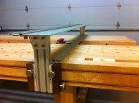
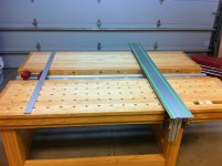
I'm coming close completing the project, I'm tinkering with the rip fence. My original thought was an Incra adjuster in the split. I'm playing with a Woodpeckers' micro adjuster. It's much smaller and easier to removed if needed. I can still go with an Incra solution if the Woodpeckers' fails to fit the bill. The fence reaches all the way to the cutting edge of the guide rail and only stands 1/2" tall. I need to complete an apron attachment bracket to lock the rip fence down really well. I'm waiting on parts from JW Winco.
The other part that I need to finish is the miter gauge. I would like the fence to extend at least to the end rail to attach it. Although I like the Incra Shop Stop, I think that it could be improved if micro adjustment could be accessed directly next to the guide rail. I've contacted a local company Fiero Fluid Power, who are going to help draw up my design to be milled. The gist is using a 10 series 80/20 with a linear bearing that is attached to a lead screw. The lead screw adjustment knob would be on the guide rail side of the miter fence. The linear bearing would move as you turn the lead screw adjustment knob. The bearing itself is able to release from the threads to be macro adjusted then re-engaged for micro adjustment. The bearing would have a hinged stop block on the material handling side of the fence. Ill post the CAD drawings when the come back from Fiero.
The other part that I need to finish is the miter gauge. I would like the fence to extend at least to the end rail to attach it. Although I like the Incra Shop Stop, I think that it could be improved if micro adjustment could be accessed directly next to the guide rail. I've contacted a local company Fiero Fluid Power, who are going to help draw up my design to be milled. The gist is using a 10 series 80/20 with a linear bearing that is attached to a lead screw. The lead screw adjustment knob would be on the guide rail side of the miter fence. The linear bearing would move as you turn the lead screw adjustment knob. The bearing itself is able to release from the threads to be macro adjusted then re-engaged for micro adjustment. The bearing would have a hinged stop block on the material handling side of the fence. Ill post the CAD drawings when the come back from Fiero.
Attachments
Sparktrician
Member
Sean, that is such a beautiful build. I think I'd have a heart attack if I laid my TS 55 in the guide track, even if there was no power cord plugged in.
[scared]
[scared]
This has inspired me to try parts from the Incra miter 5000 on my own home made MFT. One question I had from your last picture: Are you able to reach all the way across to make a full cut? Or can you easily move the saw from the right side to make a cut?
I step around the right side of the bench and walk with the saw for a full 5' rip cut. Let me also say I am 25 years old and usually just kneel up onto the bench from the stretcher. In a few more years I might do the walk around more often, I placed the kerf strip to accommodate a comfortable reach. Good luck with your project, happy to hear someone is taking their Incra's apart and using the components. Great stuff to be had inside their tools.
kylehalchin
Member
- Joined
- Jul 12, 2015
- Messages
- 2
Sean KS said:I'm coming close completing the project, I'm tinkering with the rip fence. My original thought was an Incra adjuster in the split. I'm playing with a Woodpeckers' micro adjuster. It's much smaller and easier to removed if needed. I can still go with an Incra solution if the Woodpeckers' fails to fit the bill. The fence reaches all the way to the cutting edge of the guide rail and only stands 1/2" tall. I need to complete an apron attachment bracket to lock the rip fence down really well. I'm waiting on parts from JW Winco.
The other part that I need to finish is the miter gauge. I would like the fence to extend at least to the end rail to attach it. Although I like the Incra Shop Stop, I think that it could be improved if micro adjustment could be accessed directly next to the guide rail. I've contacted a local company Fiero Fluid Power, who are going to help draw up my design to be milled. The gist is using a 10 series 80/20 with a linear bearing that is attached to a lead screw. The lead screw adjustment knob would be on the guide rail side of the miter fence. The linear bearing would move as you turn the lead screw adjustment knob. The bearing itself is able to release from the threads to be macro adjusted then re-engaged for micro adjustment. The bearing would have a hinged stop block on the material handling side of the fence. Ill post the CAD drawings when the come back from Fiero.
Sean, where did you find the apron bracket mounting piece and the pieces that clamp the 8020 down?
joe@reallyrightstuff.com
Member
- Joined
- Aug 13, 2015
- Messages
- 7
[member=17701]Sean KS[/member]
Sean, what a fine table. I'm going to build a stay-at-shop table and will incorporate much of your thinking. Question: what material did you use for the inlaid kerf guard? Looks like white nylon or Delrin. I assume you fabricated this with the dovetail profile. Where did you buy the raw material? Thanks so much for sharing. Joe
Sean, what a fine table. I'm going to build a stay-at-shop table and will incorporate much of your thinking. Question: what material did you use for the inlaid kerf guard? Looks like white nylon or Delrin. I assume you fabricated this with the dovetail profile. Where did you buy the raw material? Thanks so much for sharing. Joe
fotojoe,
UHMW Sheet
I'm pretty sure I got it at Woodcraft, but you can find the stuff lots of places. Hope that helps, have fun with the build.
UHMW Sheet
I'm pretty sure I got it at Woodcraft, but you can find the stuff lots of places. Hope that helps, have fun with the build.
joe@reallyrightstuff.com
Member
- Joined
- Aug 13, 2015
- Messages
- 7
[member=17701]Sean KS[/member]
Sean, I've been studying your beautiful bench. I see you completed the project a few years ago now. If you can spare a moment I hope you could respond to some more questions:
1. Desired Changes: After living with the workbench for a while and hopefully having a chance to use it a fair amount, what would you change, if anything?
2. Dog Holes: I see in the original sketch-up you were planning to put CNC-machined dog holes in both sides but only put them on the side with the wagon vise. Do you find you use the holes much? Are you happy with having the holes on the one side only?
3. Seasonal Expansion/Contraction: Your original plan was to use 3"-thick slabs (looks like maple). I also see that you wrapped the slabs on all sides with an apron and I wonder if seasonal expansion/contraction has caused any issues with the apron joints at the ends of the slabs?
4. Dog Hole Layout: You mentioned that your holes are 3/4" diameter so you could use Qwas dogs. I'm assuming the holes are bored all the way through the slabs. Are they on 4" centers? Do you ever use them to index 45 degree cuts or for calibrating your miter fence? If so, I expect that seasonal movement (see #3) may throw the hole positions very slightly out of square (more movement across the bench vs longitudinally) -- have you noticed anything like that?
Thanks again for sharing. I see that your build is one of the most popular on this site -- a testament to your novel hybrid design. Joe
[member=56718]fotojoe[/member]
Sean, I've been studying your beautiful bench. I see you completed the project a few years ago now. If you can spare a moment I hope you could respond to some more questions:
1. Desired Changes: After living with the workbench for a while and hopefully having a chance to use it a fair amount, what would you change, if anything?
Honestly it does the things I want it to do. I built it very slowly over the course of 2 years. So I gave myself a lot of time to think before I acted. I messed up the mounting of the wagon vise a little bit, it's not as clean of a cut out as I would've liked, but other than that, no complaints.
2. Dog Holes: I see in the original sketch-up you were planning to put CNC-machined dog holes in both sides but only put them on the side with the wagon vise. Do you find you use the holes much? Are you happy with having the holes on the one side only?
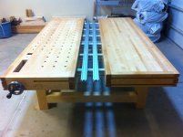
I'm really happy with the choice of only putting dog holes on one side. There are plenty of them to do alignment tasks with. And having the other side be free of holes and the wagon vise comes in handy constantly. Like not dropping small parts and hardware, or being able to use the t-tracks on either end cap for a long rail task.
3. Seasonal Expansion/Contraction: Your original plan was to use 3"-thick slabs (looks like maple). I also see that you wrapped the slabs on all sides with an apron and I wonder if seasonal expansion/contraction has caused any issues with the apron joints at the ends of the slabs?
The slab that forms the top is not a solid wood slab. It is made up of rock maple, hardboard, and plywood, in that order. The total thickness of the epoxy laminated slab is 2 3/4". Then the rails wraps that. The rails have loose tenon joinery and the wagon vise end cap has double loose tenons with brass draw bores. The rails are attached to the top with 4" bolts, there are mortises on the underside of the bench every 8" that allow the nut to slide in. The holes for the bolts are bored oversized to allow for movement. I used self locking nuts, that have not come loose due to vibration or mallet blows and the likes. Because of how I built the slab, the main "field" of the top does not expand and contract very much (it's not a machining surface, it needs to be flat enough for woodworking, which varies dramatically from woodworker to woodworker based on their particular tastes and techniques.) The apron joints have held nicely visually, and any little changes have not cause problems with functionality. I'll also add that the bench lives in a climate controlled shop. If it was sitting in a garage or otherwise exposed to huge temperature/humidity changes I would probably see problems.
4. Dog Hole Layout: You mentioned that your holes are 3/4" diameter so you could use Qwas dogs. I'm assuming the holes are bored all the way through the slabs. Are they on 4" centers? Do you ever use them to index 45 degree cuts or for calibrating your miter fence? If so, I expect that seasonal movement (see #3) may throw the hole positions very slightly out of square (more movement across the bench vs longitudinally) -- have you noticed anything like that?
Sizing and spacing on the dogs is correct. I index everything off of them, miter fence, rip fence, router set-ups of all sorts. They are accurate to a degree that it does not change my workflow (as in if it is slightly different season to season, the changes are not enough to notice in my work.) This is the main reason I did not make the top out of solid wood. That being said, I am not in the habit of taking something right from a power tool to assembly. Most everything gets hit with a plane or a chisel before it forms a joint of any kind. That being said, it's accurate enough to cross cut bed rails with just a locating pin on either end of the stock. In that scenario I had no visible light when I checked the cut against a Starrett square. That is square enough for my needs.
Thanks again for sharing. I see that your build is one of the most popular on this site -- a testament to your novel hybrid design. Joe
Hope that helps Joe, Sean
Sean, I've been studying your beautiful bench. I see you completed the project a few years ago now. If you can spare a moment I hope you could respond to some more questions:
1. Desired Changes: After living with the workbench for a while and hopefully having a chance to use it a fair amount, what would you change, if anything?
Honestly it does the things I want it to do. I built it very slowly over the course of 2 years. So I gave myself a lot of time to think before I acted. I messed up the mounting of the wagon vise a little bit, it's not as clean of a cut out as I would've liked, but other than that, no complaints.
2. Dog Holes: I see in the original sketch-up you were planning to put CNC-machined dog holes in both sides but only put them on the side with the wagon vise. Do you find you use the holes much? Are you happy with having the holes on the one side only?
I'm really happy with the choice of only putting dog holes on one side. There are plenty of them to do alignment tasks with. And having the other side be free of holes and the wagon vise comes in handy constantly. Like not dropping small parts and hardware, or being able to use the t-tracks on either end cap for a long rail task.
3. Seasonal Expansion/Contraction: Your original plan was to use 3"-thick slabs (looks like maple). I also see that you wrapped the slabs on all sides with an apron and I wonder if seasonal expansion/contraction has caused any issues with the apron joints at the ends of the slabs?
The slab that forms the top is not a solid wood slab. It is made up of rock maple, hardboard, and plywood, in that order. The total thickness of the epoxy laminated slab is 2 3/4". Then the rails wraps that. The rails have loose tenon joinery and the wagon vise end cap has double loose tenons with brass draw bores. The rails are attached to the top with 4" bolts, there are mortises on the underside of the bench every 8" that allow the nut to slide in. The holes for the bolts are bored oversized to allow for movement. I used self locking nuts, that have not come loose due to vibration or mallet blows and the likes. Because of how I built the slab, the main "field" of the top does not expand and contract very much (it's not a machining surface, it needs to be flat enough for woodworking, which varies dramatically from woodworker to woodworker based on their particular tastes and techniques.) The apron joints have held nicely visually, and any little changes have not cause problems with functionality. I'll also add that the bench lives in a climate controlled shop. If it was sitting in a garage or otherwise exposed to huge temperature/humidity changes I would probably see problems.
4. Dog Hole Layout: You mentioned that your holes are 3/4" diameter so you could use Qwas dogs. I'm assuming the holes are bored all the way through the slabs. Are they on 4" centers? Do you ever use them to index 45 degree cuts or for calibrating your miter fence? If so, I expect that seasonal movement (see #3) may throw the hole positions very slightly out of square (more movement across the bench vs longitudinally) -- have you noticed anything like that?
Sizing and spacing on the dogs is correct. I index everything off of them, miter fence, rip fence, router set-ups of all sorts. They are accurate to a degree that it does not change my workflow (as in if it is slightly different season to season, the changes are not enough to notice in my work.) This is the main reason I did not make the top out of solid wood. That being said, I am not in the habit of taking something right from a power tool to assembly. Most everything gets hit with a plane or a chisel before it forms a joint of any kind. That being said, it's accurate enough to cross cut bed rails with just a locating pin on either end of the stock. In that scenario I had no visible light when I checked the cut against a Starrett square. That is square enough for my needs.
Thanks again for sharing. I see that your build is one of the most popular on this site -- a testament to your novel hybrid design. Joe
Hope that helps Joe, Sean
joe@reallyrightstuff.com
Member
- Joined
- Aug 13, 2015
- Messages
- 7
[member=17701]Sean KS[/member]
Sean, thanks again for sharing your experience. Joe
Sean, thanks again for sharing your experience. Joe
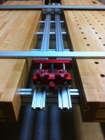
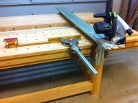
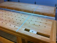
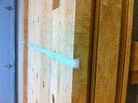
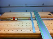
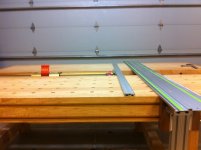
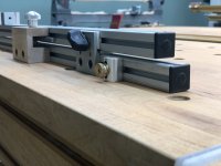
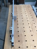
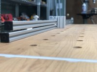
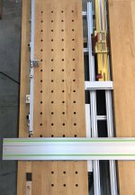
I finished up my reworking of my crosscut fence with the micro adjuster at the cut line. The idea was that it’s a pain to use a micro adjuster attached to a stop block when you can’t site your cutline at the same time. I used a rack and pinion and made a fixture to hold it. Turning the knob moves the stop block. The fence is split and the two extrusions slide parallel to each other with 80/20 unibearings. I’m liking how it works. Quick macro adjust on the flip stop, then dial it in with the adjustment knob. The fence also interfaces with my incra miter gauge for angles.
Attachments
-
 C950D22E-8076-4775-95D2-6A7E296474E3.jpeg2.8 MB · Views: 748
 -
 85FBCD3E-B16D-43C5-AB68-E2274A15E65B.jpeg2.5 MB · Views: 582
 -
 4198E6F9-54D3-4091-A183-BEB791FA0263.jpeg2.1 MB · Views: 701
 -
 D287DEBD-385C-45CE-8103-CF9F652A428D.jpeg1.8 MB · Views: 569
 -
 EA589C9F-BAB0-4515-8906-25478395432D.jpeg1.9 MB · Views: 1,166
dlu
Member
That is sweet! Are the rack-and-pinion off the shelf items? 80/20?
[member=31317]dlu@canishe.com[/member]
"That is sweet! Are the rack-and-pinion off the shelf items? 80/20?"
I wish 80/20 made racks that sit in the t track.
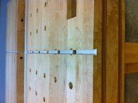
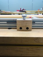
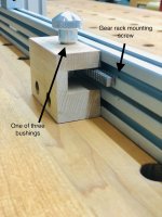
I got those buggers on Amazon. Drilled and tapped the back side of the gear rack and mounted it to the 80/20 1010 through the front with flush mounted screws. You can kinda see the screws on the front of the fence in the forth image.
www.amazon.com/gp/product/B004N630CW/ref=oh_aui_search_asin_title?ie=UTF8&psc=1
www.amazon.com/gp/product/B000LDIYE0/ref=oh_aui_search_asin_title?ie=UTF8&psc=1
The knob came attached to a thread, I filed a flat spot in the threads so the set screw of the gear had somewhere to grip.
www.amazon.com/gp/product/B00GKZCV2E/ref=oh_aui_search_asin_title?ie=UTF8&psc=1
I put some bushings into the maple fixture to keep the whole thing turning true. I think I used three of them?
www.amazon.com/Isostatics-202092-10-EF040603-Powdered-Bearings/dp/B01DJ50UBG/ref=sr_1_5?
s=industrial&ie=UTF8&qid=1547923367&sr=1-5&keywords=bronze+bushing+1%2F4
"That is sweet! Are the rack-and-pinion off the shelf items? 80/20?"
I wish 80/20 made racks that sit in the t track.
I got those buggers on Amazon. Drilled and tapped the back side of the gear rack and mounted it to the 80/20 1010 through the front with flush mounted screws. You can kinda see the screws on the front of the fence in the forth image.
www.amazon.com/gp/product/B004N630CW/ref=oh_aui_search_asin_title?ie=UTF8&psc=1
www.amazon.com/gp/product/B000LDIYE0/ref=oh_aui_search_asin_title?ie=UTF8&psc=1
The knob came attached to a thread, I filed a flat spot in the threads so the set screw of the gear had somewhere to grip.
www.amazon.com/gp/product/B00GKZCV2E/ref=oh_aui_search_asin_title?ie=UTF8&psc=1
I put some bushings into the maple fixture to keep the whole thing turning true. I think I used three of them?
www.amazon.com/Isostatics-202092-10-EF040603-Powdered-Bearings/dp/B01DJ50UBG/ref=sr_1_5?
s=industrial&ie=UTF8&qid=1547923367&sr=1-5&keywords=bronze+bushing+1%2F4
Attachments
dlu
Member
Thanks! That's very helpful. It looks like the lead time on Amazon for the racks is about a month right now (Jan 2019) - wondering what factors besides fitting drive the selection of the rack. Is the "pressure angle" critical?
[member=31317]dlu[/member]
Bummer on shipping time for the link. I was completely shooting from the hip on what pitch/angle to use. Mostly just needed one that didn’t have mounting holes pre drilled, and was narrow enough to fit on or in (I didn’t know how I was going to mount it when I ordered it) the extrusion. Someone pointed out that gear racks are traditionally for macro adjustments, and I should’ve used a fine pitch screw. That dude is probably right, but this solution felt obtainable and micro enough for my mitts.
So to answer your question, I have no idea, but I’m happy with how this thingy works. Go with the finest pitch you can find with whatever pressure angle is available I suppose.
Similar threads
- Replies
- 0
- Views
- 90
- Replies
- 6
- Views
- 1K
- Replies
- 4
- Views
- 539