VFD or replacement for 3-phase motor for Jointer

hobbes

Member
Joined
May 9, 2009
Messages
111
Ok, I need help again from the FOG community on what is the most practical, easiest solution to this dilemma. I recently acquired a used jointer for a relatively low-cost (which might have been a clue that might have given me some pause) and found out afterwards the auction that it is a 3-phase motor. What's done is done and I've researched what my options are for converting to use w/ my 220v 1-phase outlet. Basically, I can get a static or rotary generator or get a VFD (Variable Frequency Driver) or just get a new motor that is a 220v 1-phase and just replace and sell or give away the 3-phase motor.

I ruled out the generators because cost-wise it's a wash or perhaps even more $$ than it's worth and it would be the same as getting a VFD. The VFD seems like an attractive option for me since that also apparently allows for speed control on the unit as well, but involves some questions on whether the model I get would be a compatible with the motor that I have (which is a Leland 3-phase 1.5 HP motor). The jointer is an 8" Grizzzy and while the markings on the motor say 1 HP, the manual says it's 1.5 so I'm more inclined to believe the motor label. I'll attach a picture of the motor specs/label here too for reference. The other option is of course to replace the motor and if I were to go that route, does anyone have a good recommendation on which one I should choose? Get something that's the same size (or go bigger?) but obviously 1-phase version. Then in looking at new motors there's all these things I need to consider like frame size, RPM of the motor, and enclosure (which I surmise should be of the TEFC variety so that dust wouldn't get in and mess it up).

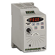
Link to a VFD that may work for my motor?:
http://www.ebay.com/itm/VARIABLE-FREQUENCY-DRIVE-INVERTER-VFD-NEW-2HP-1-5KW-p-/220692560531?pt=LH_DefaultDomain_0&hash=item33624d3a93

If I were buy a new motor, here's a slew of them to choose from (among many others):
http://www.e-motorsonline.com/products.html?cat=1&f=11_459

[attachthumb=#]

So, what do you suggest. Get a VFD and see if I can require it or get an Electrician to do that OR buy a new motor and do that myself or get an Electrician to do the same? Costwise, the VFD might be cheaper but a little more work so it's almost a toss-up. What do you suggest? Has anyone gone through this before and how did you decide which way to go?
 
Hi Hobbes,

If you don't get a satisfactory answer here (and you likely will [big grin] ), try a metal working site or group. Three-phase and VFD issues come up often on the mill_drill@yahoogroups.com that I follow, so I know a search there will bring lots of results. Probably you can find lots of results on many other metalworking groups.

Good luck, Dick
 
Hi,

I would just replace the motor. I had a rotary phase converter in my shop at one time & found it a pain to have to turn it on first before the tool you need to use. I would say up to 5 hp I would just swap out the motor. You might consider going with a 1.5 hp unit as 3 phase motors are more efficient than single phase.

Gerry
 
I'll take the other side. I would buy a rpc because as you found out 3 phase machines are less expensive. I have successfully sold all my homeowner/ light machines and bought industrial/ HD woodworking machines for about what I made on the selling of the previous units. A rpc can be wired in to a remote, but in my shop I like the added safety of no one being able to walk in and start up a machine, esp. little people. 3 phase machines have totally changed the woodworking experience for me.

Mike
 
Your initial assessment is correct. For smaller motors, the most economical solution is adding a VFD.

Store-bought static phase converters should be avoided. All they are is a motor starter, and once the motor gets up to speed, the converter disengages and the motor is left to run on single phase power. That is very bad for the motor. Rotary converters are good, but for a small motor like this, it would be the least economical solution. You're literally buying another motor plus the capacitors and controls. So the cost is higher than replacing the motor.

For a 1hp motor, you can get a VFD for just over $100. Your jointer won't really benefit from having variable speed like some other tools, but it also doesn't hurt either. (Keep in mind that even though you can change the speed significantly, you want to keep it very close to the 60 hz rate, because the motor is not designed for variable speed.)

In terms of complexity, connecting the VFD is probably easier than physically swapping out the motor. In its simplest form, it is just a matter of connecting the incoming power to the VFD, and then connecting the VFD directly to the motor (bypassing the existing on/off switch).

For your jointer, it wouldn't be much more complicated to re-purpose your existing on/off control to control the VFD. I don't know what you currently have for on/off controls, but I can easily walk you through the connections in a single forum posting.

For inexpensive VFDs, there are two popular models that are frequently discussed on the internet. The TECO FM50 is popular because it is the cheapest at $127. However, I prefer the GS1 for $134 because it has more features for only a couple dollars more money. In your case, the only difference would be that the GS1 is already set for connecting your existing on/off controls.

Oops. I just thought of something. Because this is a Grizzly jointer, if the on/off buttons are part of the existing magnetic contactor, you will not be able to reuse it. If they are separate push buttons, or even an on/off switch, you're OK. You just can't reuse the magnetic contactor. We'll cover that in a later post if necessary.

m_gs1xdrives.jpg
 
hobbes said:

Oh, I hadn't looked at your link until after I posted above. That's an impressive VFD for its price. However, because the price is so low for the size and features, I would be a little concerned about its pedigree. Because the FM50 and GS1 drives are known to me, I can stand behind my recommendation of either one of them. This one is unknown to me. Considering that you don't need the added features or size, and considering the total price is about the same, I would still recommend either the FM50 or GS1.

To give you a comparison, the VFD is similar to a 2hp GS2 with a detachable keypad. The 2hp GS2 sells for $250. Because your eBay VFD costs half that price, it scares me a little.

By the way, they don't mention it in the ad, but it appears to have the detachable keypad. You don't need that feature, but when someone does need that feature (like for a lathe), that is when I recommend the person gets the GS2 like I use on my lathe. It is not a "remote" per se. You have to buy or make a special cable to connect the detached display back to the VFD.

RemoteDisplay-lo.jpg
 
Old School Carpenter said:
I'll take the other side. I would buy a rpc because as you found out 3 phase machines are less expensive. I have successfully sold all my homeowner/ light machines and bought industrial/ HD woodworking machines for about what I made on the selling of the previous units. A rpc can be wired in to a remote, but in my shop I like the added safety of no one being able to walk in and start up a machine, esp. little people. 3 phase machines have totally changed the woodworking experience for me.

Mike

If you intend to upgrade more than one machine a rotary phase converter would be a good option but for 1 motor of that size I would just swap it out. I think the VFD is a close second but the new motor gives you new a bearing set etc. & that motor looks like it might have a little age on it. I would look for a 1.5 hp 1725 rpm in good shape used. I have not purchased a new 1.5 hp motor for a while so I might change my mind once I know the price ;)

HTH

Gerry
 
Thanks for all your input. Gave me a lot to think about and both views made sense from the perspective you provided. Given the toss-up I went with Rick's suggestion with the G1 unit, known entity is better than unknown and I don't want to have to buy twice (I've learned from those experience too many times...though some might even say this whole unit may end being that as well in the long run, but time will tell). Perhaps the unit is made in USA and that may account for the price difference versus import model or it could be component quality...hard to say and don't want to end up on the short end of the stick given that most of the features aren't what I'm looking for anyhow. Basically, all I want to be able to do is turn it on and off and plug into the outlets I have now and if there's some speed control that's just icing on the cake.

My rationale is to try the VFD since the fellow that sold me the unit said the unit runs well but just needed a converter since I didn't have 3-phase. If it should happen that the motor fails or is less than good enough then I'll look into getting the new motor. I figured that should that happen, I can always transfer the VFD onto the next unit that may take advantage of it (assume of course that is 1HP or less), but will cross that bridge if/when I get there.

I should get the unit in a few days so probably if all goes well by next week, I may actually have more than a 450 lbs. paperweight (yeah, that's the nice thing about older units is that it is built like a tank). Also, I read and am told that 3-phase imotor s more efficient so that's another reason I went with keeping the stock motor.

Rick, I'm attaching a picture of the unit and it clearly shows separate buttons or would I not be able to tell from this whether it is magnetic or not from this image? When I get the unit I'll put up my proposed wiring and I'd appreciate it if you can look it over.

[attachthumb=#]

 
hobbes said:
Rick, I'm attaching a picture of the unit and it clearly shows separate buttons or would I not be able to tell from this whether it is magnetic or not from this image? When I get the unit I'll put up my proposed wiring and I'd appreciate it if you can look it over.

Yes, those are separate push buttons that are not physically connected to a contactor. So yes, you will be able to reuse those buttons to control the VFD instead of pushing the tiny membrane switch on the VFD itself.
 
Since you've already ordered the GS1, I'll go ahead and get you started. It will come with a bound manual, but in the meantime, you can download a copy HERE.

You can mount the VFD where ever you want, but just protect the top from falling dust into the cooling vent. It can be mounted on the jointer or even on the wall behind the jointer.

You'll need a power cord for the VFD. It needs 3 wires (2 hots and a green ground. No neutral is needed.) For this VFD, 14 gauge wire is fine. You want to be able to turn off the VFD when not being used, so either use a plug or install a switch on the incoming power. Connect the 240 volt power to L1 and L2 at the top of the VFD (shown below), and the green ground wire to the ground terminal.

You will need a 4-wire cord from the VFD to the motor (also just 14 gauge). (3 hots and a green ground). This connects to the bottom of the VFD, and the other end connects directly into the motor's junction box. You do not want any switches or circuit breakers between the VFD and the motor. The VFD takes care of all of those functions, and disconnecting the VFD from the motor while the VFD is operating can damage the VFD. So your existing contactor is abandoned.

These connections are sufficient for testing your motor and VFD by using the Run/stop button on the face of the VFD. Below I will explain how to connect your on/off switches, but you don't need to do this right away for testing.

[attachthumb=#]

When you first power up your VFD, you will have to set some program parameters. Refer to your manual on how to navigate the menus. I will list the parameters you should set. Many of these aren't important, but I will bold the ones that are.

P0.00 = 240 volts (you could set this lower, but you'll get better performance at 240.)
P0.01 = 3.2 amps
P0.02 = 60 hz
P0.03 = 1750 rpm, but not important
P0.04 = 1900 rpm (sets maximum permitted speed)

P1.00 = 1 (coast to stop)
P1.01 = 2 (2 second acceleration time. Increase if VFD faults on startup)

P2.00 = 0 (general purpose motor)
P2.08 = 3 (Carrier frequency. Increase if motor is noisy)

P3.00 = 1 (external controls. Leave at zero until switches are connected.)
P3.01 = 2 (for momentary on/off switches)

P6.00 = 1 (thermal overload, standard motor)
P6.02 = 0 (no restart on power loss)

===========================================
On/Off switches
For a "proof of function" test, you don't need to have the switches connected. To start and stop the jointer, just press the run/stop button on the face of the VFD. However, for this test, make sure to leave program item P3.00 = 0, otherwise it will disable the start button on the VFD.

Everything I have written so far was based on your on/off switches being momentary switches. However, after looking at the picture again, I am not positive this is correct. The Stop switch is currently recessed, so these might be connected to a single toggle switch. If the start switch stays recessed after you press it, then it is a toggle switch. If that is true, then you'll have to set program P3.01 = 1 instead of 2. The two versions are described on page 4-21 of your manual.

In either configuration, DI2 (digital input #2) is not used for your jointer. You don't need to reverse the motor.

Speaking of that, if your motor turns backward during your initial test, then simply swap T1 and T2 on the VFD. (Reversing any 2 wires on a 3-phase motor reverses the motor. That's universal to all 3-phase motors and has nothing to do with the VFD.)
 
Wow, lots going on there. Definitely would not have figured all that out on my own so thank you for that! And I'm sure whoever else comes along after me will benefit from this.

I've got a couple questions from what you posted:

Q1: You recommended setting it to 240V for P0.00 but wouldn't that overload my 220v circuit? I know that there is some variation in voltage for the circuits but I didn't think the variance would be that wide.

Q2: I was thinking for the 4-wire cord from the VFD to the motor, I can probably use the existing cord (you'll notice that it is a 4-prong plug in that jointer picture). Would that work or you suggest a new one?

Probably will have more when I get this hot potato in my hands.  ???  ;D

 
hobbes said:
Q1: You recommended setting it to 240V for P0.00 but wouldn't that overload my 220v circuit? I know that there is some variation in voltage for the circuits but I didn't think the variance would be that wide.

Unfortunately, common lexicon uses the terms "110" and "220" so much that it sticks and people don't realize that the nominal voltages are actually 120 and 240. I am not entirely sure how this came about, but I suspect it might have to do with the nameplate ratings on motors. For a motor that is intended to operate on a 240 volt circuit, it will have a nameplate rating of 220 or 230. These numbers signify that the motor can withstand operating at that "under-voltage" condition. So people see that nameplate, and the number sticks in their head.

Your motor is actually rated to operate at either 208 volt 3-phase or 240 volt 3-phase. These are two different electrical systems in the U.S. So your motor is designed to be able to operate on either of these common 3-phase systems. Therefore, you could set the VFD output voltage to anything between 208 and 240. (It is not uncommon for a 3-phase motor to be rated only for 208 volts, but yours isn't one of them.)

As for overloading your circuit, no, this is not an issue. First off, your circuit is 240 volts. Secondly, the internal DC voltage inside the VFD is much higher than 240 volts. It's complicated to explain, but the internal voltage of the VFD is over 300 volts DC.

hobbes said:
Q2: I was thinking for the 4-wire cord from the VFD to the motor, I can probably use the existing cord (you'll notice that it is a 4-prong plug in that jointer picture). Would that work or you suggest a new one?

I hadn't noticed that cord previously, but was privately hoping that is exactly what you would have had. Yes, you can reuse that cord for the connection between the VFD and the motor.
 
Rick got my VFD over theweekend, almost ready to put this together but want to make sure I don't burn this motor from doing something stupid. So here's what I'm going to do.
1) Wire the new 3-prong 240V cable to L1, L2, and Gnd on GS1.
[attachthumb=#]
After I do that and with nothing else added on the output side, I should be able to enter all those parameters in the Gs1, correct?
Then stop the GS1, unplug from power outlet, and continue to wire the output as follows:
2) I'l bypass the switch entirely and connect each of the wire from the jointer's existing plug to the motor.
Here is a picture of the inside of the panel where it currently shows them connected to the switch. After I direct connect them that switch will just be sitting there doing nothing.
[attachthumb=#]
Here's a capture of the panel diagram in case that's useful.
[attachthumb=#]
Finally this is the GS1 VFD, not sure how i should wire the existing switch (from image 2 above) to the GS1. Looking at the picture above is that do-able? The switch does toggle for ON and OFF.
[attachthumb=#]
Except for using the current switch, after wiring the output I should be able to plug back in the power and turning the unit ON and if all goes well it should run. Did I miss anything?
 
It is late and my brain is shot. So I don't want to try to interpret what I think I am reading from what you are meaning.

Yes, connect that power cord of picture #1 to the L1, L2 of the VFD.
No, don't power up the VFD until after you connect the motor.

I think I am reading you correctly in that you understand that the original power cord needs to be disconnected from where it is connected at the top of the contactor in picture #2 and moved to the bottom wires leading to the motor. This cord will now connect T1,T2,T3 at both the motor and the VFD.

So the only change from what you suggested is that you complete the wiring to the motor before you power up the VFD. It wouldn't be a big deal either way, just a safety in case you accidentally started the VFD during programming.

Don't worry about the on/off controls for now. Just focus on connecting power to the VFD and connecting the VFD to the motor. Trying to do too much at once may lead to a mistake or miscommunication.

 
Oops. I didn't look at picture #3 right away. Your existing On/Off buttons are not switches. They are purely mechanical, and press against the old contactor to activate it. You will not be able to reuse your original buttons because they are not really switches.

So given this new information, you can completely remove the entire box shown in pictures 2 and 3 from you jointer. It cannot be re-used.

You'll need to either use the membrane switches on the VFD, or get some other on/off control.

 
Good news! I wired it up, programmed it as instructed, cross my fingers, and mumbled a few words, then turned it ON, and it works perfectly the first try!

Here's the ugly spaghetti wiring job that I did after removing the switch from the junction box.
[attachthumb=#]
Here it is tidied up a bit, but of course this can't fit in this enclosure so I'll have to look for an enclosure that actually fits this.
[attachthumb=#]
Here's me trying to find an enclosure at Home Depot that might fit, but of course there's no exact match and ones that are remotely close cost nearly as much as the VFD.
[attachthumb=#]
So I don't think HD is the right source for this, nor do they have ones that appears to include a fan as shown in the min. requirements diagram from the manual. I'm looking for one at least sized like shown.
[attachthumb=#]
And here's the before and after on a quick piece of stock that I tested on the jointer. This is one instance where the weight of the unit was a blessing in that there was very little vibration and it just felt effortless powering through that cherry like it was harden butter.
[attachthumb=#]
Pretty happy this isn't a 450 lbs. pile of useless steel. Thanks Rick for being so patient in guiding me through this process! All I need now is to properly mount it in a nice enclosure, play around with adjustments on the jointer, and I'll be back to making wood chips again. I learned a lot from this experience and hopefully others will learn from this too.
 
You don't need to mount the VFD inside an enclosure. You just need to prevent dust from falling into the cooling vents on the top. So you can mount it anywhere you wish.

The On/Off switches I showed above actually came with my lathe, but you can get more modern ones. I have a set that a manufacturer gave me, but I haven't showed them before. All you need are 2 momentary switches with one being normally open and one being normally closed. These are common, and I will see if I can find a source for you later.

I am sorry, but once again it is late at night and I am too tired to go dig this up at the moment. I'll try to remember to do this in the morning.

Oh, P.S. You can use any switch you want to use. The link in your post didn't work, but I know the type you are referring to. So if you pick a switch, I will tell you how to hook it up. It makes no difference what switch it is. You can use that switch, or you can use the momentary switches that I hope to be able to show you in the morning. It is all just a matter of what you prefer, and a simple program change.
 
Idec was actually who I was thinking about last night because that is the switch that I had laying around. While I was looking for the catalog to pull up a part number, I stumbled on the fact that Automation Direct (where the VFD came from) already supplies these pushbutton switches (not from Idec but nearly identical).

The switch you could use is this one. GCX3152 You just need a box with a 22mm hole to install it in. Oh, you don't necessarily need a box. You can just drill a 22mm hole in the sheetmetal base of the jointer. (the square bezel is removable, and behind it is a 22mm post with a retaining nut to secure it to the sheetmetal.)

m_gcx3152.jpg


There is also nothing wrong with the rockler switch. I found that page after all, and then remembered that I once had that same switch when I wrote the instruction manual for one of their router tables. However, you will need to rewire this switch. It has one male 120V plug and one female 120v plug. One of these cords would be removed, and the other one would have to be reconnected to the switch differently, and the 120v plug cut off. This isn't a momentary switch, so it would be wired into the VFD with only 2 wires and the VFD programmed for that type of control.

So given the two choices and the complexity of each, I would get the one from Automation Direct. Plus it is only $10 versus $26.
 
Back
Top