First off, thank you to everyone that took the time to check their bases and post info, I appreciate it.
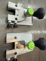
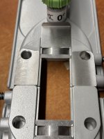
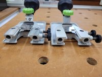
I stand corrected, the machining on top of the base does seem to signify the 0* base.
However that machining can't be what makes it attach to the motor at 0*, as that's not the mounting surface for the horizontal position.
Either the 2 dowel holes and the face angle on the end are different between the two, or the lower base is different.
My bet is that top base is what is different.
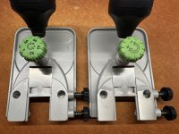
I also didn't have a difference in the lower base between the 1.5* and 0*.
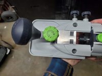
View attachment 1
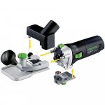
View attachment 2
Crazyraceguy said:
I was completely wrong on this, last night. I looked at mine today and they are exactly the same as pictured. The machining is on the Zero degree base, so I would assume that they are all made as 1.5 degree in the first place. Then some are pulled out and modified to zero degree.
The machining on top still confuses me though, since you can mount the motor vertically in those holes. I just used one that way a few days ago, which is somewhat rare for me, I use them horizontally mostly.
That is the 1.5 degree base, but the bit isn't angled in the vertical orientation. It has to be the drilling and registration face on the end of the zero degree that changes it.
Coen said:
Yeah because they designed it with the top of the 1.5 base being parallel for vertical mount. Then they tilted the whole thing 1.5 degrees to make the 0 base, but had to cut flat the top to allow for vertical use again.
I think they're machined different to begin with. The dowel holes and mating surface on the thin end are what change the angle I think. That has to be machined anyways. Easier to have both bases case the same and then just change the machining I would think?
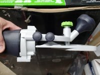
This morning I was playing with mounting the motor as you have pictured (I've never done it before), and with both of the 1.5* bases I had ( I don't have a 0* base, I made a mistake there).
I didn't spend a lot of time, but I did notice a couple of things.
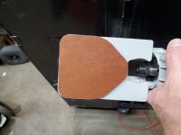
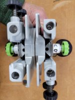
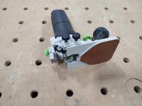
I tried mounting it vertically on the horizontal base because one of the pictures on the Festool page for the 0* base has it mounted that way, though it seems to have some attachments that aren't available here? I wonder if this has anything to do with the machining on the top? Is/was there a different use for this? Overseas or here?
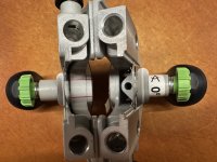
View attachment 3
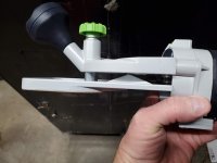
I couldn't get the motor to stabilize on the base. It wobbled a little bit. I wonder if that's why the 0* base is machined? To more securely mount? Or maybe it was just me, I didn't try very hard (no time).
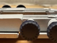
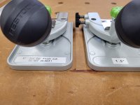
One of my bases has slightly less room in the "gap". The area the router bit sits in when the base is mounted horizontally. My router bit was just hitting the end with one of the bases. I'll try to add a picture of that later.
When mounting the motor in the base vertically the sliding steel cover is very very close to the router collet.