Packard
Member
On the Shinwa, can’t you use the millimeter markings to more accurately interpolate the mid points?
smorgasbord said:Your 'Shinwa with a DRO' comment, though has me thinking about retrofitting or building the sliding hypotenuse type design with a DRO. Mine Shinwa is 60cm long so there's plenty of ruler travel.
-snip-
Maybe an adopted Shinwa design using a linear DRO along a 60cm or so length would be a good way to set an angled fence on a tablesaw sled. Hmmm...
Packard said:On the Shinwa, can’t you use the millimeter markings to more accurately interpolate the mid points?
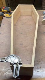
Packard said:For this demonstration, I used 3/4” plywood about 6” x 12”.
The first step was to set the saw angle using a 30/60/90 triangle that is part of a $4.00 set. It’s intended audience is high school students studying geometry.
The first photo shows the board with the opposite ends cut on the angle.

I next sliced the board into 6 equal sized pieces.

I taped it up into a hex. I am confident that with proper clamping all the miters will close up. It might close up if I used packing tape instead of masking tape. If it did not close up, I would tweak the angles until it did, or I would burnish the joints to close up any outside gap.

I re-taped the hexagon with a strong packing tape. It tightened up the joints to what I would call “ideal”.
The photo hosting site I use (IMGUR) is “over capacity”. I will try posting the image a little later.
Addendum: IMGUR got its act together. Here is the hexagon assembled with stronger packing tape. You can enlarge the image to better see the joints.

The set up triangle was part of this Staedtler “math” set, which was $3.79 at staples. It included a protractor, 30/60/90 triangle,, 45/90/45 triangle, 6” ruler.
These are all small items and perfect for my table saw.
https://www.staples.ca/products/455884-en-staedtler-4-piece-math-set-instruments

smorgasbord said:I'll have to see what measurements I can pull off the Shinwa itself for the triangle legs length (pivot to pivot) but my observation is that the spacing between degree is very non-linear. Even with them being closer at 20º and 100º than at 50º, the amount of closeness is still different between 90º and 100º than between 20º and 30º. So, I'll have to do the math, but yeah, I should be able to use my long digital caliper on the Shinwa to set pretty accurate non-integer angles.
Packard said:I meant, for example, you want 45.3 degrees.
So you set it at 45 degrees, then count the number of hash marks on the mm scale when you shift to 46 degrees. So let’s say there were 6 hash marks between 45 ans 46 degrees on the mm scale.
So 45.33 degrees would be 45 degrees plus two hash marks on the mm scale. So to get 45.3 degrees I would set it at 45 degrees plus two hash marks (scant).
It would be more accurate than just eyeballing the degree setting.
Not really math, more like counting (the hash marks).
Why am I calling these “hash marks” and not “millimeters? So as not to confuse what is really being measured.
Borrowing the mm hash marks seems like an easy way to up the accuracy of your interpretations.
squall_line said:smorgasbord said:I'll have to see what measurements I can pull off the Shinwa itself for the triangle legs length (pivot to pivot) but my observation is that the spacing between degree is very non-linear. Even with them being closer at 20º and 100º than at 50º, the amount of closeness is still different between 90º and 100º than between 20º and 30º. So, I'll have to do the math, but yeah, I should be able to use my long digital caliper on the Shinwa to set pretty accurate non-integer angles.
I don't have the mental acuity right now (or maybe just the patience) to determine whether it would be the sine or cosine, but yes, the distance between the degree markings should be variable.Packard said:I meant, for example, you want 45.3 degrees.
So you set it at 45 degrees, then count the number of hash marks on the mm scale when you shift to 46 degrees. So let’s say there were 6 hash marks between 45 ans 46 degrees on the mm scale.
So 45.33 degrees would be 45 degrees plus two hash marks on the mm scale. So to get 45.3 degrees I would set it at 45 degrees plus two hash marks (scant).
It would be more accurate than just eyeballing the degree setting.
Not really math, more like counting (the hash marks).
Why am I calling these “hash marks” and not “millimeters? So as not to confuse what is really being measured.
Borrowing the mm hash marks seems like an easy way to up the accuracy of your interpretations.
See above. It's not an evenly-divisible relationship, it's either the sine or cosine, so they're closer or further depending on where you are on the scale.
Packard said:I meant, for example, you want 45.3 degrees.
So you set it at 45 degrees, then count the number of hash marks on the mm scale when you shift to 46 degrees. So let’s say there were 6 hash marks between 45 ans 46 degrees on the mm scale.
So 45.33 degrees would be 45 degrees plus two hash marks on the mm scale. So to get 45.3 degrees I would set it at 45 degrees plus two hash marks (scant).
It would be more accurate than just eyeballing the degree setting.
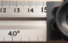
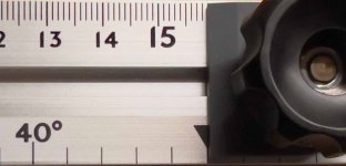
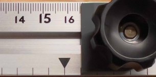
smorgasbord said:Packard said:On the Shinwa, can’t you use the millimeter markings to more accurately interpolate the mid points?
Sort of, if you're comfortable with math. Here are close-ups of the 44º, 45º, and 46º settings:
[attachimg=1]
[attachimg=2]
[attachimg=3]
44º is close to 15.2cm. Maybe 15.21
45º is close to 15.9cm. Probably 15.88
46º is over to 16.5cm. Probably 16.53
That makes 6.7mm from 44º to 45º, and 6.5mm from 45º to 46º, if my eye-balling of sub-millimeters is correct. So, yeah, assuming [member=3513]PaulMarcel[/member] 's observation on the BCTW AMPv2 that linear interpolation between integral degrees also applies to the Shinwa (they have different geometries since the AMPv2 has legs that are the same length [or about], while the Shinwa's fixed legs are not the same lengths as each other so maybe that affects interpolation accuracy), then yeah that could be done.
More potentially exciting is that this means instead of actually trying to figure out how to install a DRO on the Shinwa, or building my own Shinwa design with a DRO, I could use a long digital caliper's depth rod to make a very accurate setting. I bought a 12" (300mm) digital caliper at Taylor Toolworks recently since it was on overstock sale at a price too good to pass up, and could use that to set the Shinwa up to about 65º - maybe higher angles if I add a fixed length rod extension or try to measure from the depth stop rod end to the fixed jaw to double the capacity. Hmm. I'll see if I can try that out in the next couple days (I'll be back in my shop Tuesday morning). Maybe this is a reason to get the medium size Shinwa instead of the big one I got?
I'll have to see what measurements I can pull off the Shinwa itself for the triangle legs length (pivot to pivot) but my observation is that the spacing between degree is very non-linear. Even with them being closer at 20º and 100º than at 50º, the amount of closeness is still different between 90º and 100º than between 20º and 30º. So, I'll have to do the math, but yeah, I should be able to use my long digital caliper on the Shinwa to set pretty accurate non-integer angles.
[member=3513]PaulMarcel[/member] , if you do get a Shinwa I'd be interested in a comparison of accuracy at the integer marks compared to your BCTW AMPv2.
Packard said:On the middle image above, If I draw a line straight up from the 44 degree mark, I see 7 hash marks separating the 44 degree mark and the 45 degree mark, so each hash mark is equal to .143 degrees.
Packard said:This all seems more like machine shop tolerances than woodworking tolerances. It would not affect me or how I work. I get as close as I can in the initial set up and then make a test. I add or subtract a hair and then either test again or proceed.
Packard said:Injection molded draftsmen’s triangles from a major supplier of drafting equipment are exceptionally accurate.
When you think on it, if you are going to pop $75,000 to $200,000 for a mold, you are going to carefully check accuracy before signing the acceptance letter.
If you are looking for a 30,45,60 or 90 degree angle, you would be hard put to come up with something more accurate than a draftsman’s triangle.
A cnc might (might) match it, but it had better be machined from a very stable material. No wood product would be up to snuff.
Packard said:If you are looking for a 30,45,60 or 90 degree angle...
smorgasbord said:Packard said:If you are looking for a 30,45,60 or 90 degree angle...
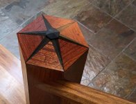
We're not. Again, check out Paul's Angle Madness Blog and Videos (see up thread for link). I could post my newel toppers yet again if you really want....
Packard said:I was thinking of Pijol’s original post where he complained about the failure to get repeatable results with the Woodpeckers unit.
Packard said:How often are other angles called out?