GarryMartin
Member
- Joined
- Jun 11, 2011
- Messages
- 1,939
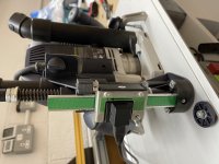
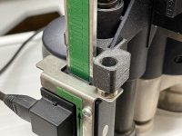
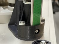
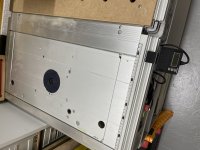
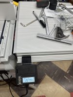
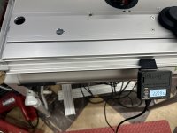
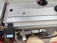
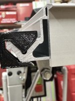
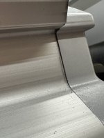
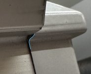
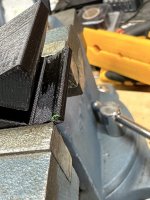
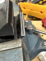
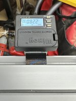
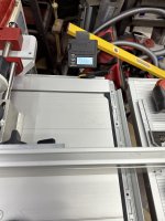
I did something similar some time ago, but I wanted a solution that did not make any changes to the CMS plate or its components, so I toyed around with a 3D-printed solution. I never got around to finessing it because it worked fine at a particular point and I then moved on to other things, but if anyone wants to try it for themselves, I've attached the STL files you'll need as a ZIP file. All it needs is some longer bolts for the bottom part where it connects with the plate and the screws etc. from the Wixey install.
Otherwise things are friction fit or you can apply a little glue if you feel the need.
Hope someone finds it useful.
[attachimg=1][attachimg=2][attachimg=3][attachimg=4][attachimg=5]
Otherwise things are friction fit or you can apply a little glue if you feel the need.
Hope someone finds it useful.
[attachimg=1][attachimg=2][attachimg=3][attachimg=4][attachimg=5]