You are using an out of date browser. It may not display this or other websites correctly.
You should upgrade or use an alternative browser.
You should upgrade or use an alternative browser.
CMS VL sliding table hack
- Thread starter msnelling
- Start date
bkharman
Member
- Joined
- Jul 1, 2013
- Messages
- 2,019
Awesome job Michael!
I had grand plans of doing something similar, but had thoughts of routing a groove in the MFT to use that side was even going to build a sled for small parts and crosscutting. If you wouldn't mind, please share more details here (or via PM) as you make progress.
Also love to see more folks with a similar setup as me but progressing it. LOVE IT!!
Cheers. Bryan.
Sent from my iPhone using Tapatalk
nclemmons
Member
Please share more details!
Thanks -
Thanks -
Mark Johnson
Member
- Joined
- Oct 27, 2016
- Messages
- 39
Yes please - more details!
I have been considering this myself as well, but not got around to doing anything yet so seeing what you have done would be most helpful.
Thanks for sharing.
Mark
I have been considering this myself as well, but not got around to doing anything yet so seeing what you have done would be most helpful.
Thanks for sharing.
Mark
Hi Bryan thanks for the enthusiastic response it was great fun to do!
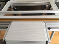
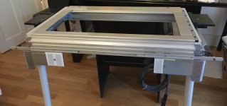
This is not a step-by-step guide but I guess the picture tells the story.
Cut the top of the sliding table rail so that it leaves a 27mm X 5mm channel. Insert the 40mm side of a 40mm X 30mm X 5mm aluminium angle into the channel and bolt through with enough play for height adjustment. Bolt the miter channel on top of the 30mm side of the angle making the holes in the angle oversize for lateral alignment to the VL. That's it!
The oversize holes in the angle allow for +/- 2mm lateral and height adjustments. In practice adjustments were in the range of 1mm with an accuracy of 0.03mm to parallel along the entire length of the rail. The 5mm thick angle has added a certain stiffness to the rail and requires considerable lateral pressure to deflect it, hopefully more than you would experience in ‘normal’ woodworking conditions. I also added a pair of additional holes to the sliding table rail so it can be mounted centrally when working with narrow stock.
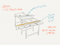
My plan is to mount an INCRA LS-25 on the MFT/3 and an INCRA 1000-HD miter gauge on the sliding table. After squaring the MFT/3 and VL, calibration would be : - 1) Square the LS-25 to the MFT/3, 2) Extend the LS-25 fence over the VL and square it with the miter slot, 3) Square the 1,000-HD miter gauge to the miter slot.
The even Grander plan is to have dedicated OF-2200 and TS-75 CMS inserts so I can keep my TS-55 and OF-1400 free for bench work.
Watch this space!
This is not a step-by-step guide but I guess the picture tells the story.
Cut the top of the sliding table rail so that it leaves a 27mm X 5mm channel. Insert the 40mm side of a 40mm X 30mm X 5mm aluminium angle into the channel and bolt through with enough play for height adjustment. Bolt the miter channel on top of the 30mm side of the angle making the holes in the angle oversize for lateral alignment to the VL. That's it!
The oversize holes in the angle allow for +/- 2mm lateral and height adjustments. In practice adjustments were in the range of 1mm with an accuracy of 0.03mm to parallel along the entire length of the rail. The 5mm thick angle has added a certain stiffness to the rail and requires considerable lateral pressure to deflect it, hopefully more than you would experience in ‘normal’ woodworking conditions. I also added a pair of additional holes to the sliding table rail so it can be mounted centrally when working with narrow stock.
My plan is to mount an INCRA LS-25 on the MFT/3 and an INCRA 1000-HD miter gauge on the sliding table. After squaring the MFT/3 and VL, calibration would be : - 1) Square the LS-25 to the MFT/3, 2) Extend the LS-25 fence over the VL and square it with the miter slot, 3) Square the 1,000-HD miter gauge to the miter slot.
The even Grander plan is to have dedicated OF-2200 and TS-75 CMS inserts so I can keep my TS-55 and OF-1400 free for bench work.
Watch this space!
Attachments
Mark Johnson
Member
- Joined
- Oct 27, 2016
- Messages
- 39
Very interesting. How did you or are planning to square the CMS-VL to the MFT3?
Thanks, Mark
Thanks, Mark
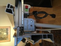
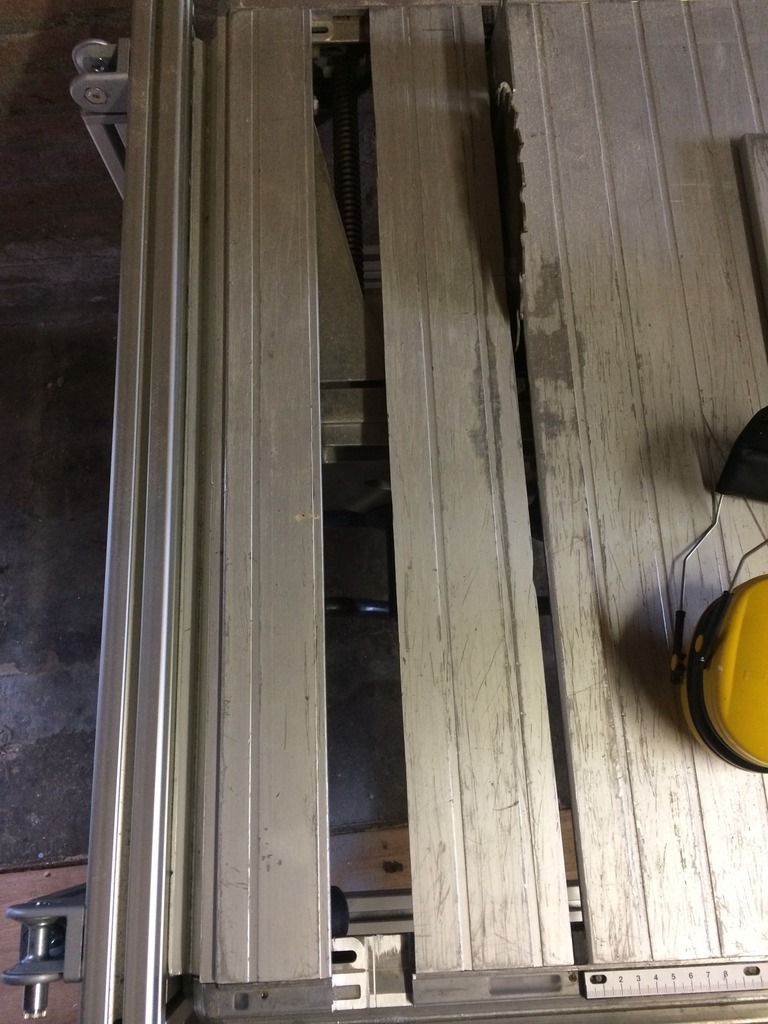
Calibrating the miter slot to the VL
Have added a rudimentary micro adjust using a couple of Guide rail connectors in the T slot behind the rail.
Primary calibration of the miter slot to the CMS (to 0.1mm) is done by adjusting the bolts on the miter track, but finer adjustments (to 0.01 the resolution of my digital caliper) are done via micro adjust screws located in a pair of Guide rail connectors in the T track behind the rail.
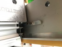
Procedure is: - 1) measure for alignment between the edge of the VL and the miter track at either end of the table 2) At the end with the highest reading lock off the back nut of the cap head screw so that it just makes contact with the rail 3) at the end with the lower reading slacken off the adjacent locking knob on the rail and micro adjust the cap head screw clockwise by a quarter turn 4) re-tighten the locking knob and re-check the reading with the caliper 5) repeat steps 3&4 until the measurements at both ends are equal, finally lock off the back nut on the micro adjust.
Checking the calibration over a number of days there doesn't appear to be any drift or creep due to flexing, it remains to be seen what will happen when I actually put it to some heavy use!
Have added a rudimentary micro adjust using a couple of Guide rail connectors in the T slot behind the rail.
Primary calibration of the miter slot to the CMS (to 0.1mm) is done by adjusting the bolts on the miter track, but finer adjustments (to 0.01 the resolution of my digital caliper) are done via micro adjust screws located in a pair of Guide rail connectors in the T track behind the rail.
Procedure is: - 1) measure for alignment between the edge of the VL and the miter track at either end of the table 2) At the end with the highest reading lock off the back nut of the cap head screw so that it just makes contact with the rail 3) at the end with the lower reading slacken off the adjacent locking knob on the rail and micro adjust the cap head screw clockwise by a quarter turn 4) re-tighten the locking knob and re-check the reading with the caliper 5) repeat steps 3&4 until the measurements at both ends are equal, finally lock off the back nut on the micro adjust.
Checking the calibration over a number of days there doesn't appear to be any drift or creep due to flexing, it remains to be seen what will happen when I actually put it to some heavy use!
Attachments
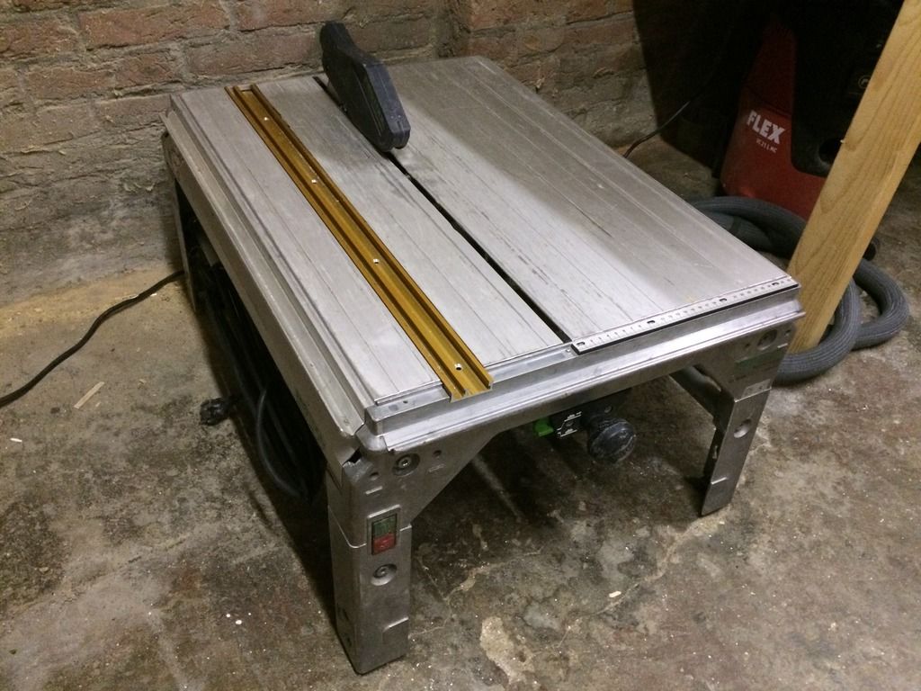
Nicely done! That should be very handy to use. I don't understand why Festool doesn't use miter slots. I added one to my CS70 as part of my saw/router table:
(Link to whole project)
(Link to whole project)
Hi LN thanks for the feedback ... your CS70 project was one of the inspirations for mine ... the inclusion of a miter slot for the CMS would be a game changer ... but then they would have to produce an INCRA quality miter gauge ... we live in hope!
Similar threads
- Replies
- 0
- Views
- 347
- Replies
- 0
- Views
- 554
- Replies
- 0
- Views
- 199