(The name is an Aussie joke; Also, apologies for the giant pictures - I can't get the site's upload to work properly, and photo bucket wants money to behave properly)

I had a lot of fun with this one! Kinda got away from me a bit...
Way back, in the pre-COVID world, I cobbled up the traditional dual bucket separator for my Festool vac. I thought I'd use it for a few months until I sorted out something more permanent. Two and a half years later...
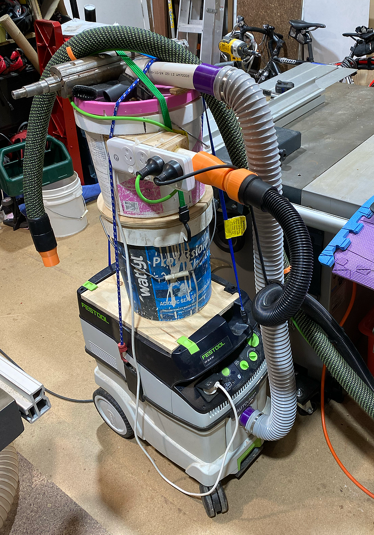
While it worked well and cost peanuts, it's cumbersome, top-heavy, prone to filling up without notice, and occasionally falling over - despite some internal bracing, the collector bucket occasionally collapsed. I had it bungie-tied down with a Felder thicknesses cutter block weighing it all down. It made quite a bang whenever that lot came crashing down!
I like Festool, and can just about rationalise the price of their tools - I've only ever fretted about the price before buying them. Never after. They just work. Where Fe$tool takes The Michael is when it comes to accessories - hundreds of dollars for a router trenching template which is essentially a few bits of acrylic with some knobs; overpriced clamps... and so on. So when they came out with a 'cyclone' separator for $400-odd, I just rolled my eyes. I expected there to be some clever engineering involved, but when I finally got to look at one at my local dealer, I found no such cunning. It was just a couple of systainers with a very rudimentary plastic cyclone and basic baffle.
It inspired me to get back to sorting out my own.
My current project goals are
-Learn to drive the new AvidCNC
-Learn to drive Fusion360
and for the separator
-stability & systainer-like attachment to the vac
-visual indicator that it's full
-easy emptying
-ability to leave both my hoses plugged in (changing hoses. such a pain. #firstworldproblems!)
I've been fiddling with the design for ages, but the CNC finally inspired me to press on with it.
Originally the concept looked something like this:
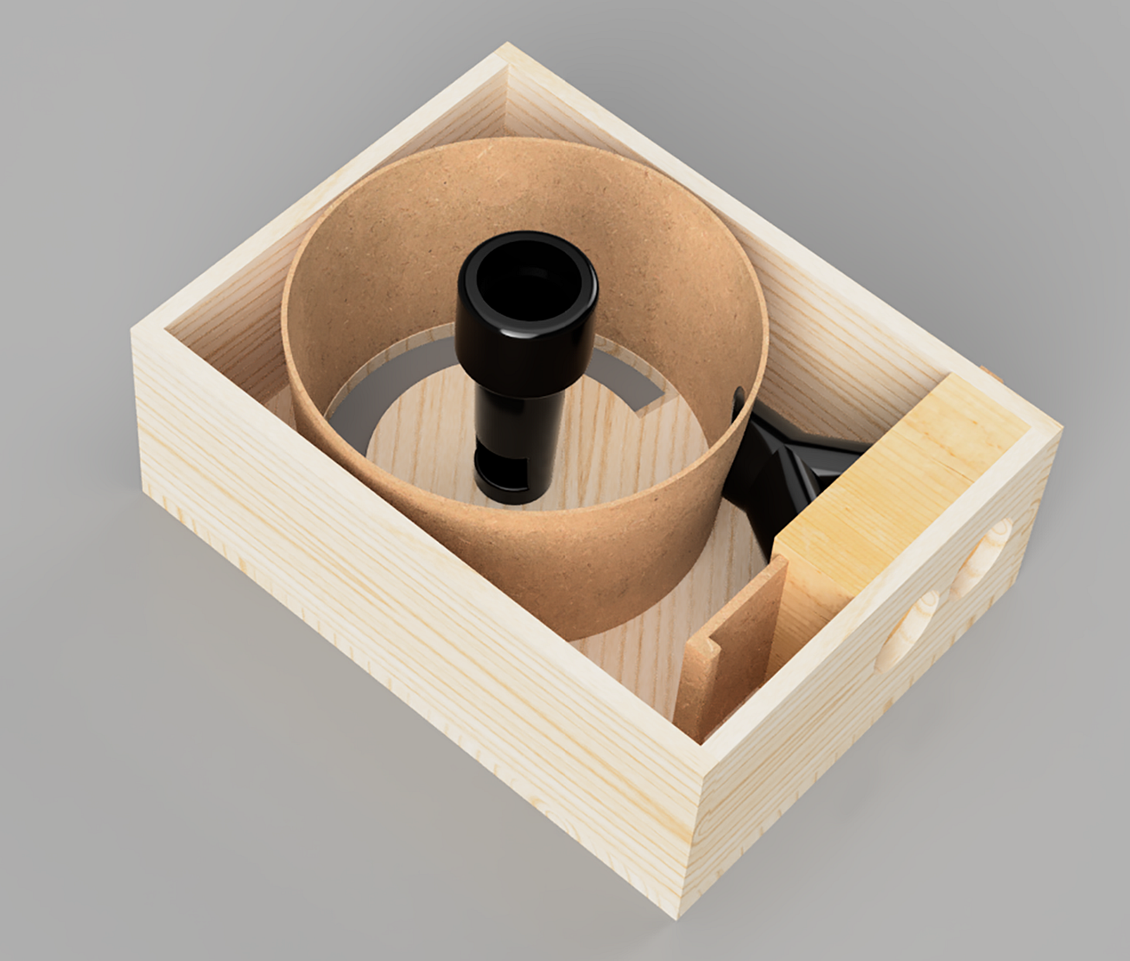
Simple conventional sliding blast gate, and a baffle made of bent MDF. I did experiment with some 3mm melamine-lined MDF, and it's definitely do-able, but I ultimately decided to go a different way...
Version 2:
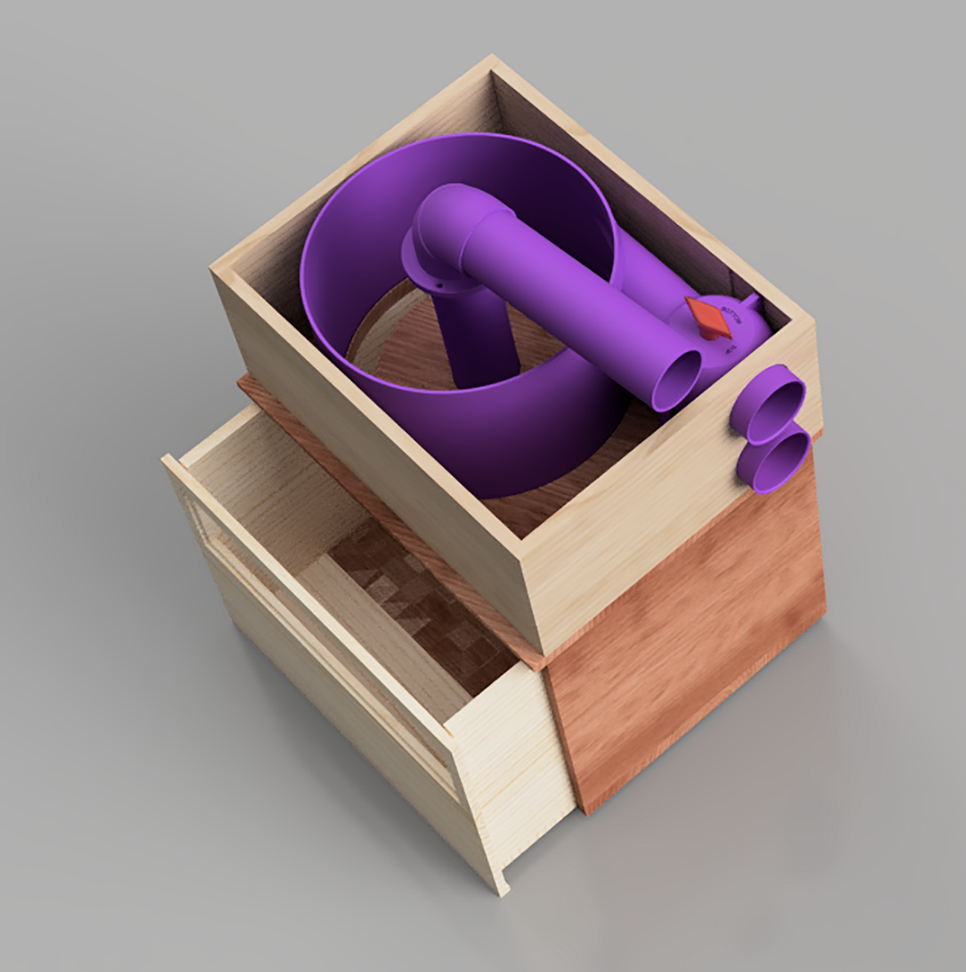
I stumbled across an interesting idea for a rotating blast gate on Thingiverse. The claim was that they clog less easily than conventional gates, and don't lose efficacy. The downside is that they're quite bulky. I decided it would be a good Fusion360 exercise to make a parametric model of the gate so I could plug in any hose size, and have the software spit out the correctly sized bits for 3D-printing. And then I could possibly double it up and use it as a linked dual gate for the collector...
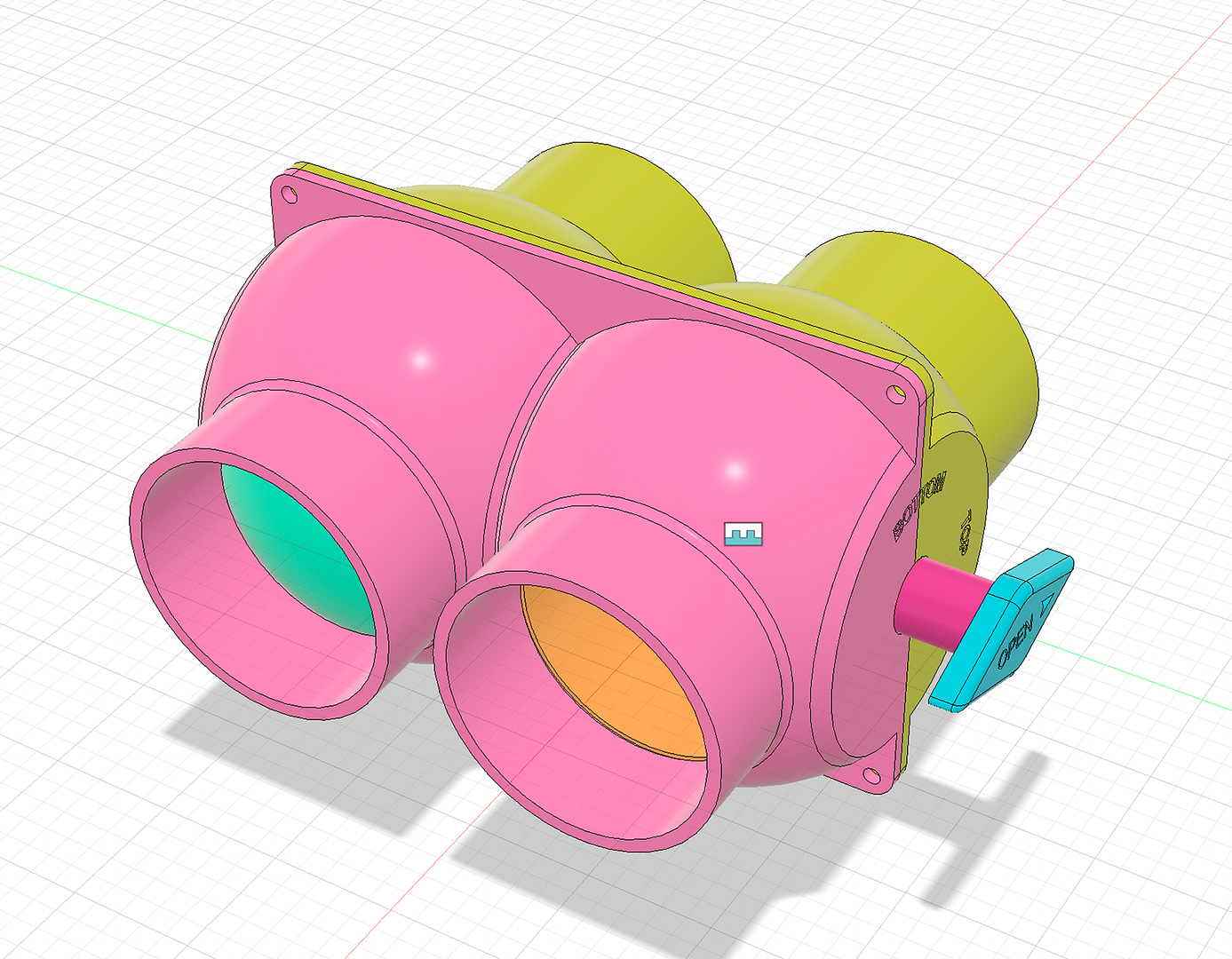
Fusion360 is pretty cool. You can build the model, put it all together, and then use joints to make it all work like it should...
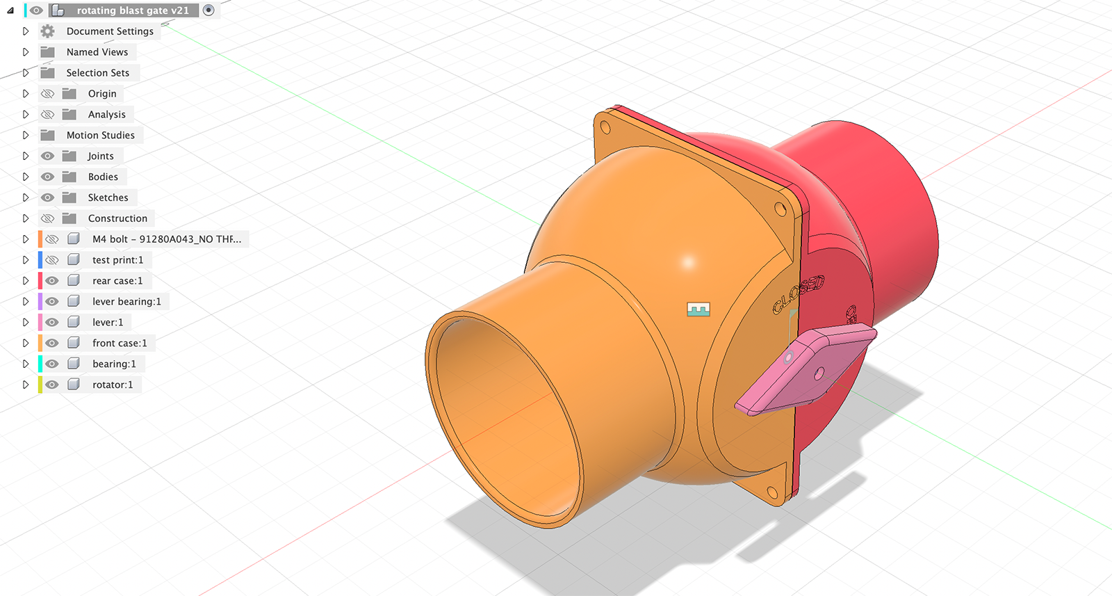
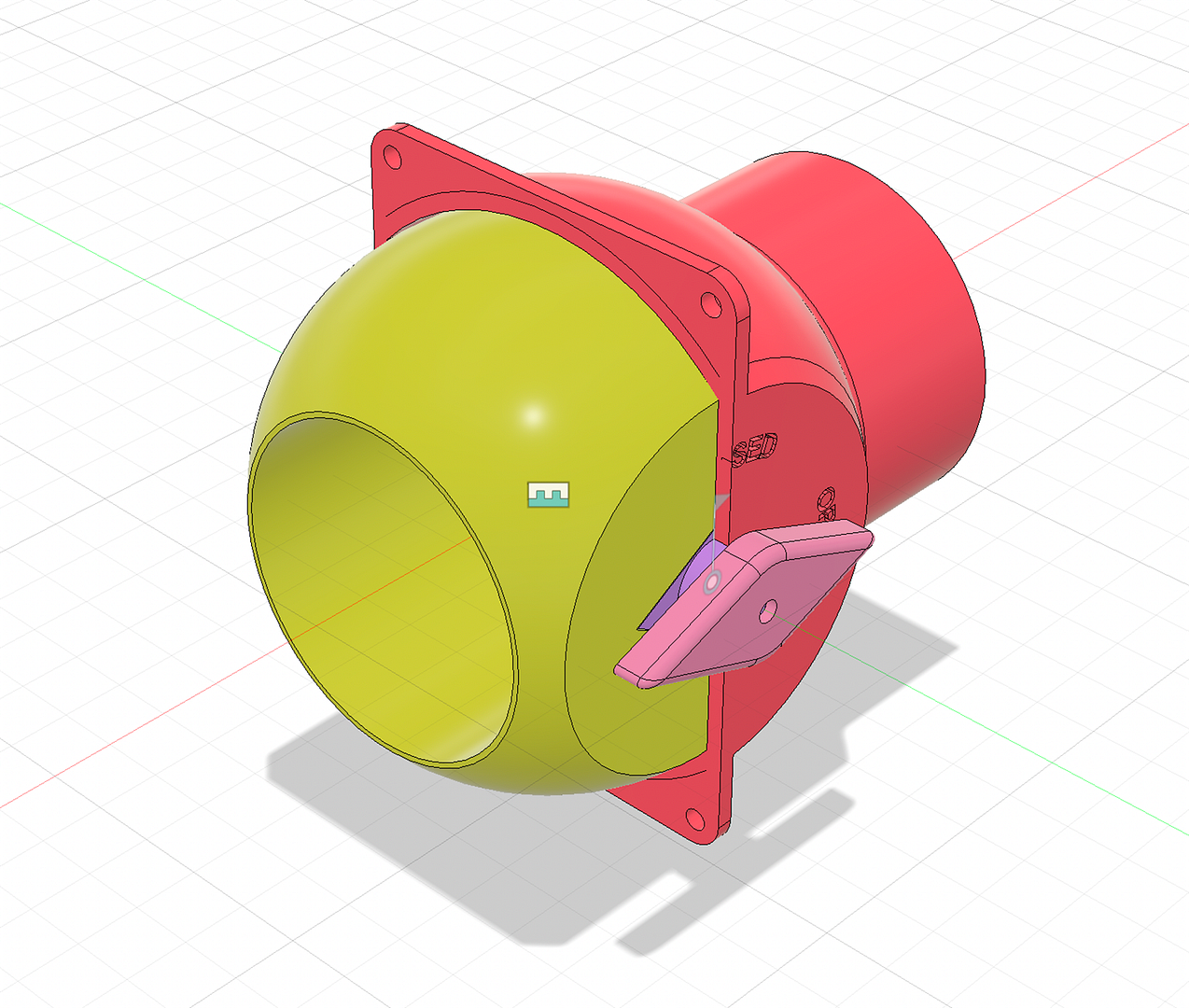
Within F360, I can make the gate operate as it would in the real world, and make sure it all moves as it should.
Spring is coming (here in the southern hemisphere), and the gates are breeding...
Sectional views are another useful feature of CAD. Tolerances are pretty tight in the gate to make sure that it's all sealed up, so useful to check that things can still move.
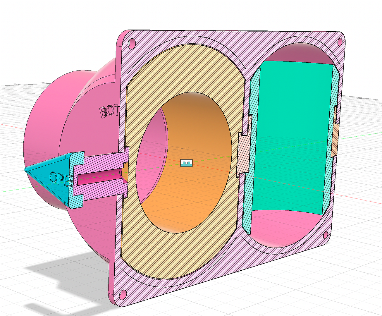
The gate model can then be inserted into the dust separator model, and because its linked, any alterations I make to the original gate will then update the model in the dust separator. Pretty cool.
Final model:
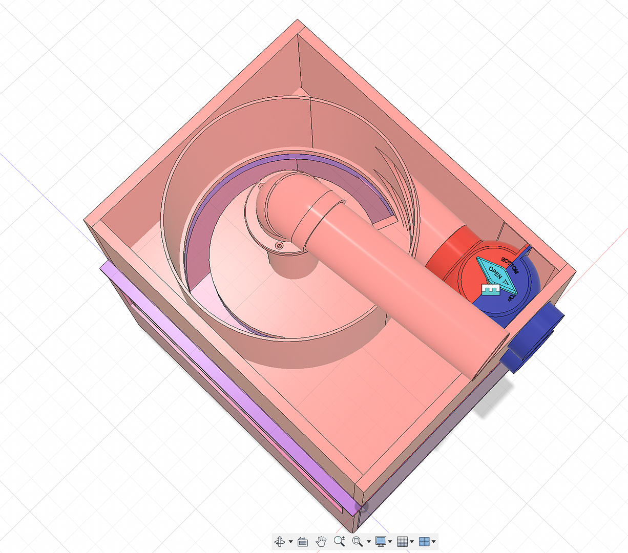
It was a pretty satisfying experience to turn that model into a bunch of CNC tool paths and 3D print-able parts, send them to the two machines, and see the whole thing start to become a physical reality.
Lots of bits to put together. Blast gate rotators needed a bit of sanding to get rid of any print artefacts and ridges so they moved smoothly.
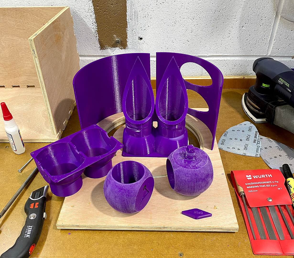
Check out those star-trek like intake pipes!
Bit of a 3d-printfest glue up
.png)
You can see the evolution of my modelling abilities in the pipe bends - from the original bend (far left, on the pipes), printed as one piece (too many supports needed), to a split design (little to no support needed), to flanged, to split flanged to accommodate pipe clamps.
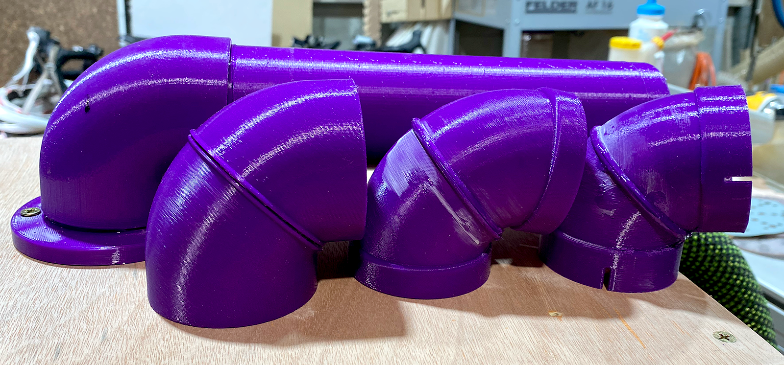
The F360 model for the bend is also parametric, so I can just plug in the pipe diameter, and angle of the bend, and it spits out the correct model. I needed a 90deg bend, a 95 and an 85 for this build, so having a Fusion's parametric power was great.
While I waited for parts to print (a long time!), I carried on with getting the CNC to butcher the wood. Again, lots of F360 to learn.
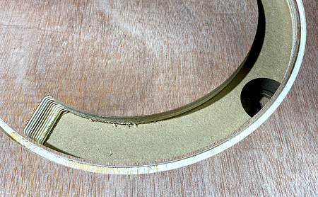
Here's a basic roughing cut for the Thien Baffle, including the ramp down into the collector box:
There were several double-sided parts, and I had to cut, test fit, modify the model and recut several times. The beauty of having my CNC spoilboard set up like the Festool MFT with bench dogs was that I could take the cut piece off, play with it, and then put back in exactly the same position to machine off that extra millimetre. One of my major learning experiences with the CNC during the project was this on-the-fly adjustment process.
Ikea flat-pack of parts (do you guys have Ikea in the States?) . I messed around with several build options for the different assemblies, including my Fusion360 parametric finger-jointed box design.
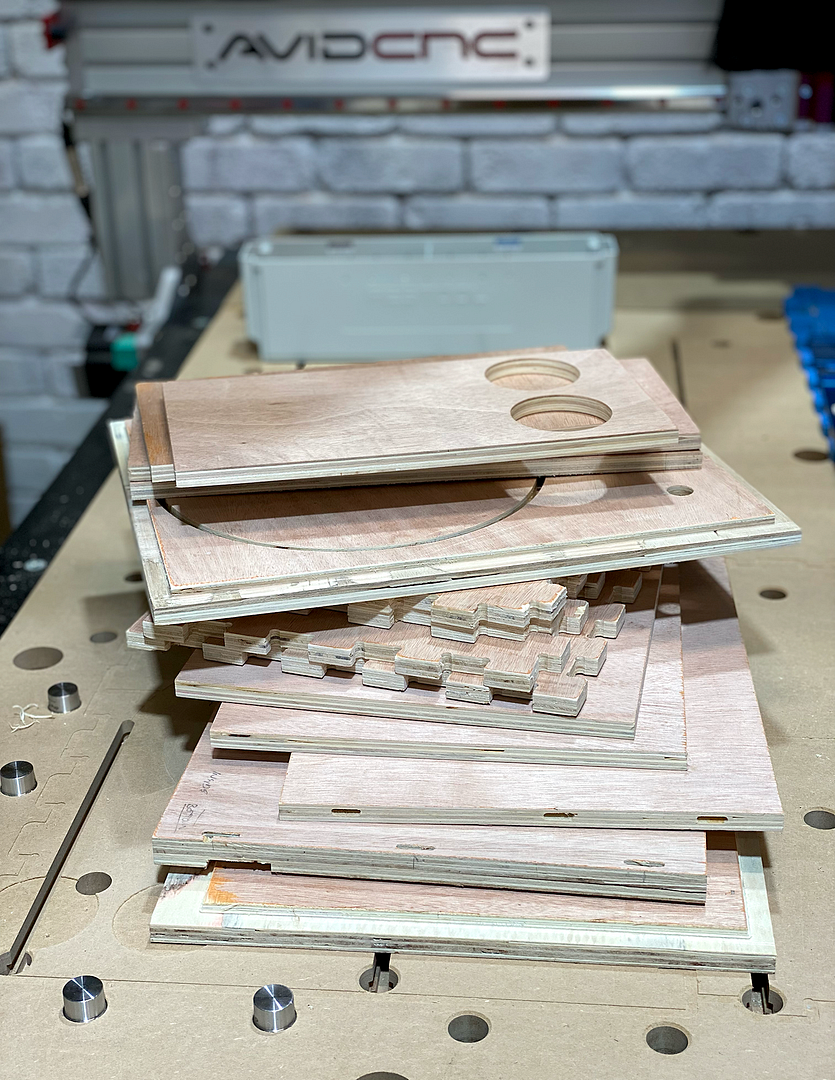
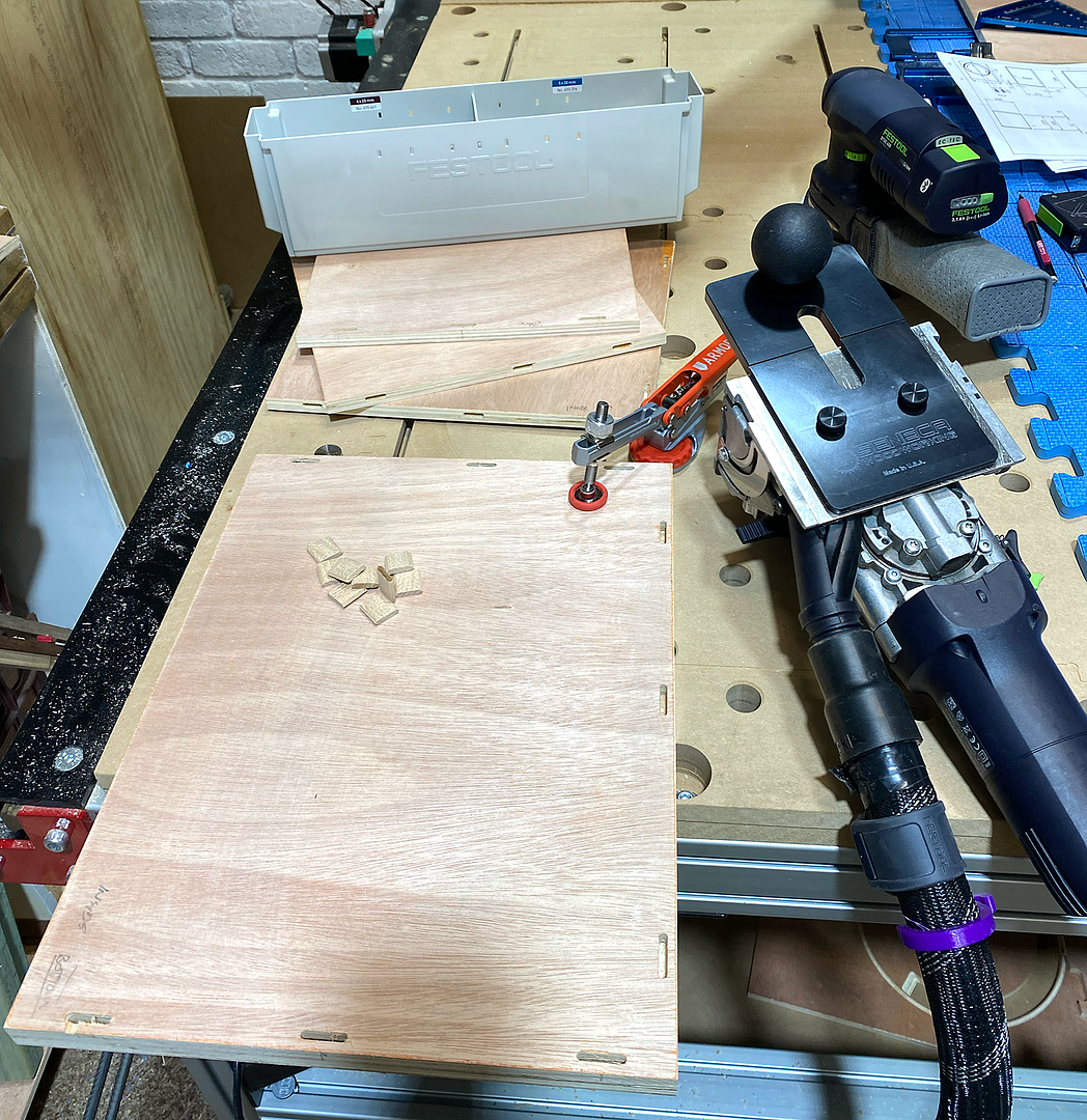
I'm using cheap ply, so I still find dominos are the best for pulling everything into line, and straightening out those inevitable warps and curves.
CNC precision:
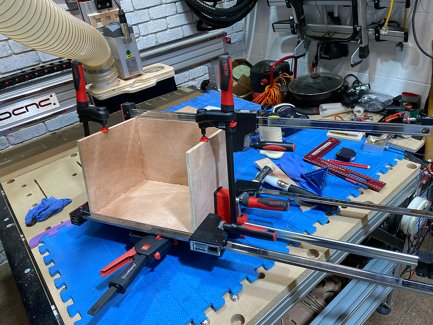
Time to start putting it all together:
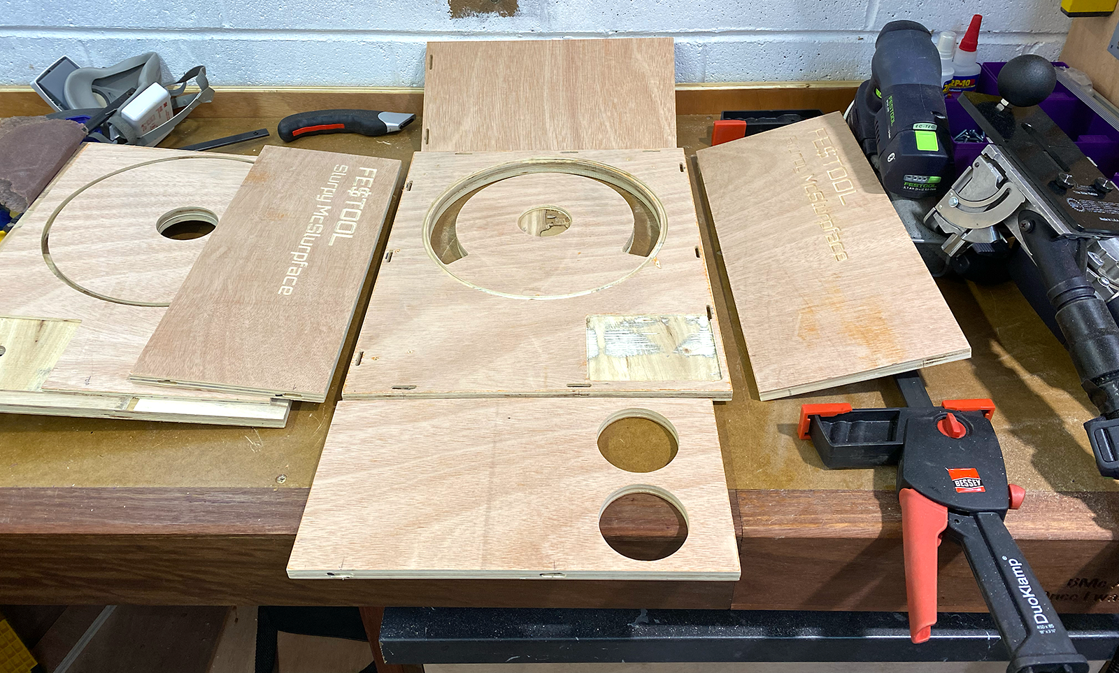

Eagle-eyed views will notice that the CNC does writing quite well!
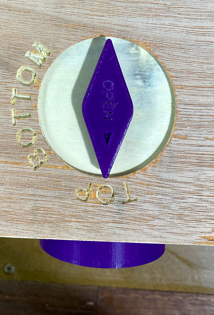
Blast gate control:
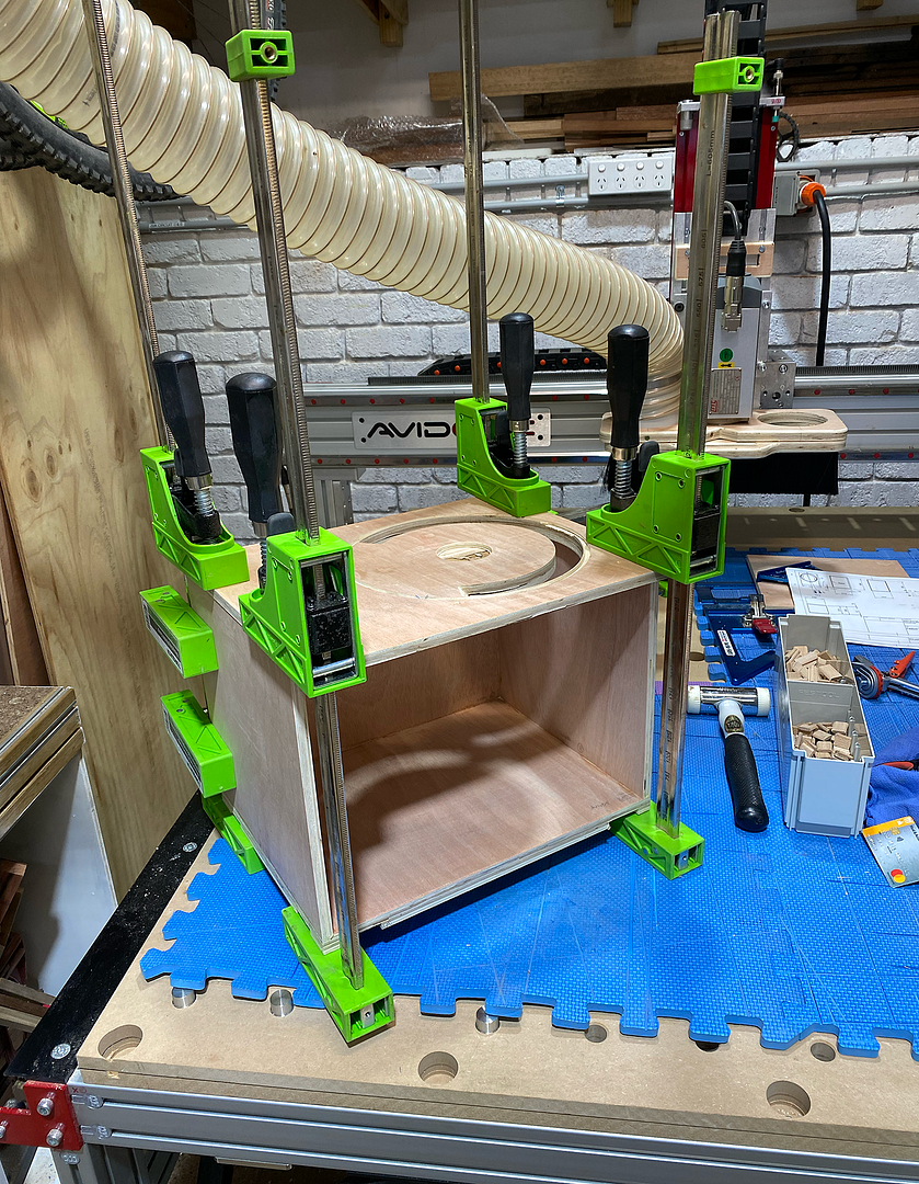
Clamps, clamps, clamps
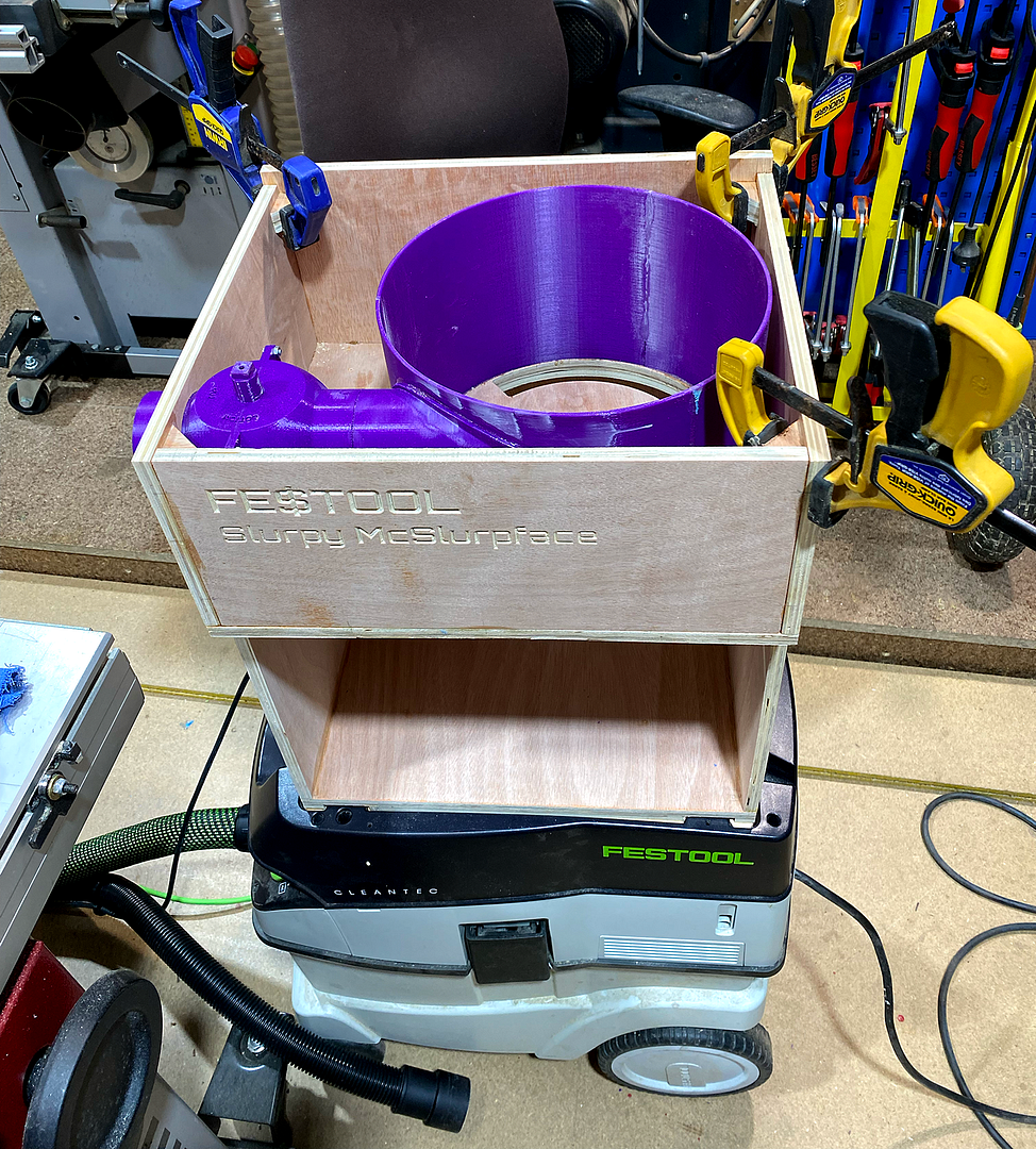
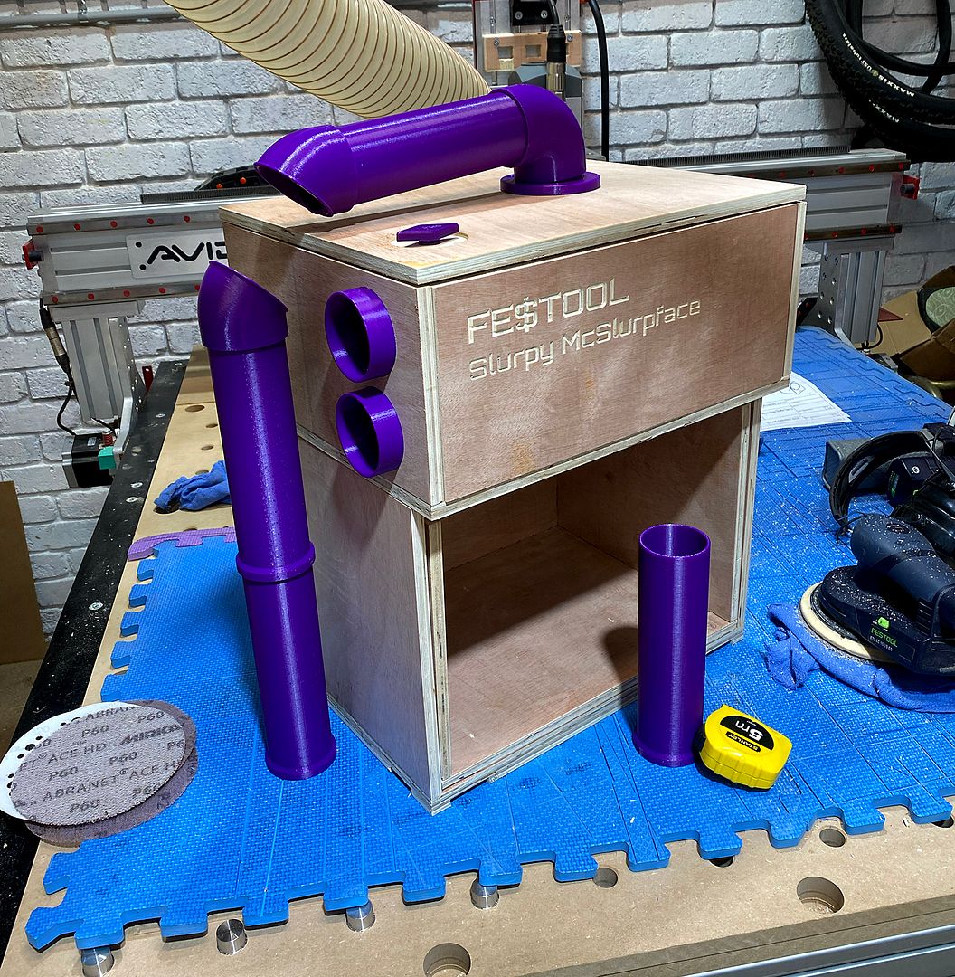
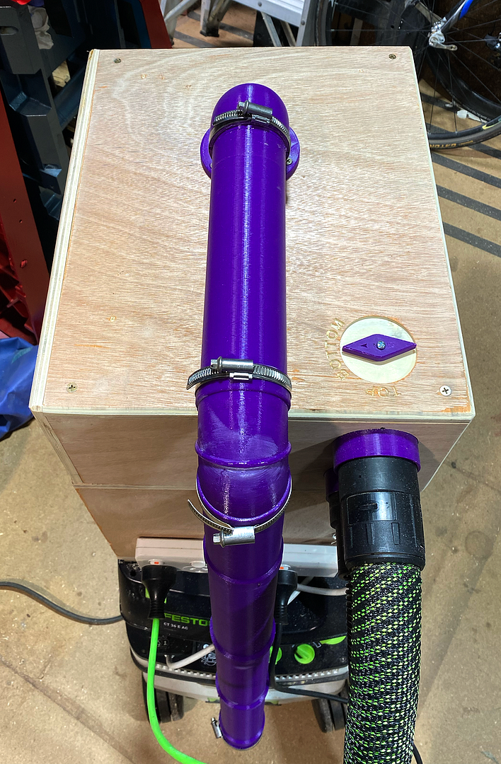
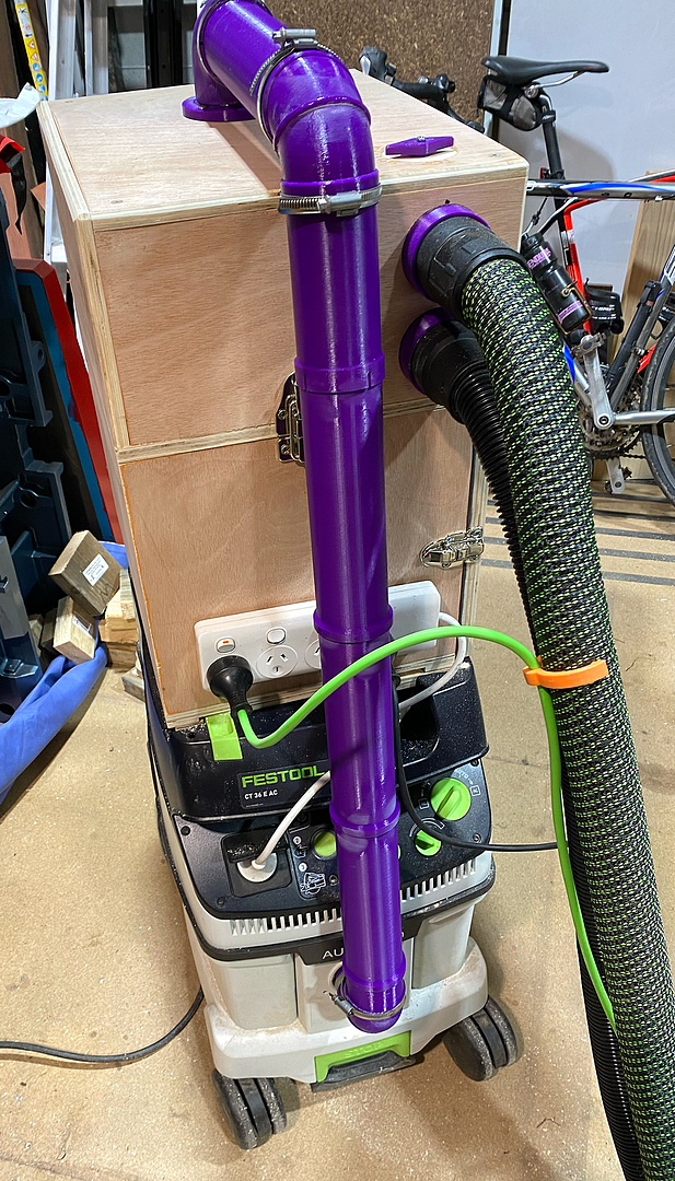
And there she is: Slurpy McSlurpface (name is an Aussie joke). Dual hose Fe$tool Dust Separator.
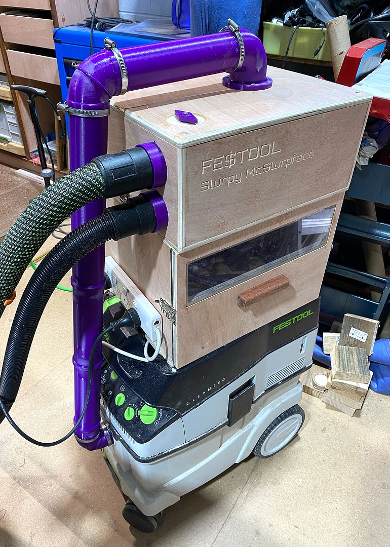
My printer can only print up to 210mm high, so I had to do the pipe in sections, and join them. Still got a few bits to do - some hooks for the hoses, and a power cable tidy (I have the original Festool attachment for this somewhere in all the clutter of the shop.
Carcass is more complex than necessary - it would be simpler to make it all one box with the Thien separator in the middle, but I have some more zany ideas to experiment with at some stage, so I wanted to be able to remove the cyclone section.
Pretty happy with the result. I haven't done the traditional remove-the-vac-bag-and-suck-up-a-pile-of-dust-and-see-how-much-gets-past-the-separator test yet, but it appears to be working pretty well. And it's easy to empty!

I had a lot of fun with this one! Kinda got away from me a bit...
Way back, in the pre-COVID world, I cobbled up the traditional dual bucket separator for my Festool vac. I thought I'd use it for a few months until I sorted out something more permanent. Two and a half years later...
While it worked well and cost peanuts, it's cumbersome, top-heavy, prone to filling up without notice, and occasionally falling over - despite some internal bracing, the collector bucket occasionally collapsed. I had it bungie-tied down with a Felder thicknesses cutter block weighing it all down. It made quite a bang whenever that lot came crashing down!
I like Festool, and can just about rationalise the price of their tools - I've only ever fretted about the price before buying them. Never after. They just work. Where Fe$tool takes The Michael is when it comes to accessories - hundreds of dollars for a router trenching template which is essentially a few bits of acrylic with some knobs; overpriced clamps... and so on. So when they came out with a 'cyclone' separator for $400-odd, I just rolled my eyes. I expected there to be some clever engineering involved, but when I finally got to look at one at my local dealer, I found no such cunning. It was just a couple of systainers with a very rudimentary plastic cyclone and basic baffle.
It inspired me to get back to sorting out my own.
My current project goals are
-Learn to drive the new AvidCNC
-Learn to drive Fusion360
and for the separator
-stability & systainer-like attachment to the vac
-visual indicator that it's full
-easy emptying
-ability to leave both my hoses plugged in (changing hoses. such a pain. #firstworldproblems!)
I've been fiddling with the design for ages, but the CNC finally inspired me to press on with it.
Originally the concept looked something like this:
Simple conventional sliding blast gate, and a baffle made of bent MDF. I did experiment with some 3mm melamine-lined MDF, and it's definitely do-able, but I ultimately decided to go a different way...
Version 2:
I stumbled across an interesting idea for a rotating blast gate on Thingiverse. The claim was that they clog less easily than conventional gates, and don't lose efficacy. The downside is that they're quite bulky. I decided it would be a good Fusion360 exercise to make a parametric model of the gate so I could plug in any hose size, and have the software spit out the correctly sized bits for 3D-printing. And then I could possibly double it up and use it as a linked dual gate for the collector...
Fusion360 is pretty cool. You can build the model, put it all together, and then use joints to make it all work like it should...
Within F360, I can make the gate operate as it would in the real world, and make sure it all moves as it should.
Spring is coming (here in the southern hemisphere), and the gates are breeding...
Sectional views are another useful feature of CAD. Tolerances are pretty tight in the gate to make sure that it's all sealed up, so useful to check that things can still move.
The gate model can then be inserted into the dust separator model, and because its linked, any alterations I make to the original gate will then update the model in the dust separator. Pretty cool.
Final model:
It was a pretty satisfying experience to turn that model into a bunch of CNC tool paths and 3D print-able parts, send them to the two machines, and see the whole thing start to become a physical reality.
Lots of bits to put together. Blast gate rotators needed a bit of sanding to get rid of any print artefacts and ridges so they moved smoothly.
Check out those star-trek like intake pipes!
Bit of a 3d-printfest glue up
You can see the evolution of my modelling abilities in the pipe bends - from the original bend (far left, on the pipes), printed as one piece (too many supports needed), to a split design (little to no support needed), to flanged, to split flanged to accommodate pipe clamps.
The F360 model for the bend is also parametric, so I can just plug in the pipe diameter, and angle of the bend, and it spits out the correct model. I needed a 90deg bend, a 95 and an 85 for this build, so having a Fusion's parametric power was great.
While I waited for parts to print (a long time!), I carried on with getting the CNC to butcher the wood. Again, lots of F360 to learn.
Here's a basic roughing cut for the Thien Baffle, including the ramp down into the collector box:
There were several double-sided parts, and I had to cut, test fit, modify the model and recut several times. The beauty of having my CNC spoilboard set up like the Festool MFT with bench dogs was that I could take the cut piece off, play with it, and then put back in exactly the same position to machine off that extra millimetre. One of my major learning experiences with the CNC during the project was this on-the-fly adjustment process.
Ikea flat-pack of parts (do you guys have Ikea in the States?) . I messed around with several build options for the different assemblies, including my Fusion360 parametric finger-jointed box design.
I'm using cheap ply, so I still find dominos are the best for pulling everything into line, and straightening out those inevitable warps and curves.
CNC precision:
Time to start putting it all together:
Eagle-eyed views will notice that the CNC does writing quite well!
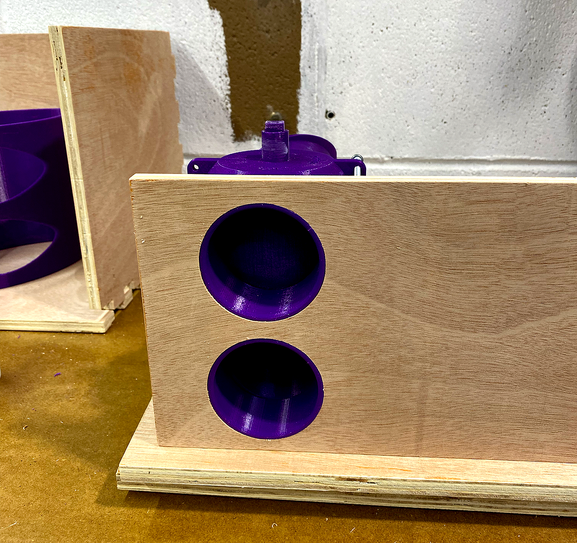
Blast gate control:
Clamps, clamps, clamps
And there she is: Slurpy McSlurpface (name is an Aussie joke). Dual hose Fe$tool Dust Separator.
My printer can only print up to 210mm high, so I had to do the pipe in sections, and join them. Still got a few bits to do - some hooks for the hoses, and a power cable tidy (I have the original Festool attachment for this somewhere in all the clutter of the shop.
Carcass is more complex than necessary - it would be simpler to make it all one box with the Thien separator in the middle, but I have some more zany ideas to experiment with at some stage, so I wanted to be able to remove the cyclone section.
Pretty happy with the result. I haven't done the traditional remove-the-vac-bag-and-suck-up-a-pile-of-dust-and-see-how-much-gets-past-the-separator test yet, but it appears to be working pretty well. And it's easy to empty!