CTL 26 circuitboard diagrams

Coen

Member
Joined
Aug 25, 2010
Messages
3,187
Location
NL
I have a 230V CTL 26 E, build year 2020 that when turned on, gave some arcing and a puff of white smoke and doesn't give a sign of life ever since.

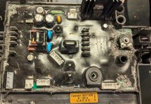
I have taken out the circuit board and found nothing visibly wrong. No blown caps, no burned parts. The problem however... is that it is encased in epoxy (?). I have removed a bunch of it with a soldering iron, however, the PCB has some holes in it and the epoxy has flown underneath too, so I don't know how to free the board from it's 'basket'.

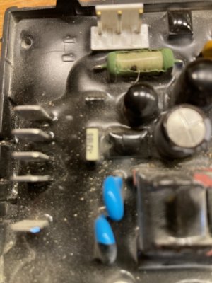
The potentiometer behind the main switch did have a funny smell. I have removed the epoxy around it and removed it's cap. It is from PIHER (probaby a PT15) and market 50K842M. I cannot match that to their naming topology however. I did measure the potentiometer and it ranges from 0 Ohm to about 14 kOhm. That is however 'in circuit', so that will most likely distort the measurement. Otherwise I would have expect 0 to 50 kOhm. This potentiometer tell the CTL to either be in auto or manual-on.

The problem is however, I don't have a diagram and the epoxy makes it impossible to draw one myself. So if anyone has it, or has had a similar problem before (and a solution) I would be happy to hear it.

I do have another (older) 230V CTL 26 E that I can compare measurements with. However, I am somewhat reluctant to swap out the PCB 1:1 in case the motor blew the PCB. The older PCB does have significantly less epoxy on it, but the entire surface is still invisible.

I could of course just buy a new PCB at €125 but for my wallet' and environments sake I'd rather just replace the broken parts. Like that potentiometer is only ~70 cents.

This is where I am at now;
[attachimg=1]
 

Attachments

  • PXL_20240302_214722240_crop.jpg
    PXL_20240302_214722240_crop.jpg
    1.3 MB · Views: 970
Coen, it would be a simple matter to pull the existing pot out and wire in a new 50Kohm one to try, but are you sure it's the switch between auto/manual? Doesn't make sense to me to use a variable component as a switch, unless it's not a pot?
 
A few weeks ago the exact same thing happened to my CTL 26 E AC. If I am not mistaken I posted about it here on the forum.

By the way, that puff of white smoke was really obnoxious. I suspect it must have been bad for your health to breath in whatever that stuff was. Luckily I managed to evade most of it. I hope for you you did too.

After inspection of the board I couldn't find the cause of it either. There was no visible damage at all. In the end I gave in and sent the machine to Festool to repair it. They replaced part 203974 (Electronic CTL AC 230V FL VP) and after that the machine was OK again. The part cost €128 excluding VAT (but I reckon you already knew that). The total cost for the repair was just above €200, including VAT.

If you do find out which component it was, then I'd be interested to know. It still bugs me I couldn't find out.
 
luvmytoolz said:
Coen, it would be a simple matter to pull the existing pot out and wire in a new 50Kohm one to try, but are you sure it's the switch between auto/manual? Doesn't make sense to me to use a variable component as a switch, unless it's not a pot?

Not so simple because the underside of the PCB isn't accessible because the epoxy also went underneath it so it's pretty much 'glued' over a huge portion of it's bottom surface. So unsoldering the pot will probably result in it being destroyed. Then putting in a new one... maybe with a small pool of solder on each of the three holes, using three irons, then drop it in. Or I have to just cut a hole in the basket so I can reach the underside of the PCB near the pot.

Yeah, it makes no sense to me either, but since the main switch just does the same in both manual and auto (close the 2 poles) the potentiometer has got to be the thing that makes it able to distinguish between 'on' and 'auto'. Btw, the connector from the main switch has six poles and five wires; four to the switch and one goes straight to another contact on the same connector.

Also makes no sense to me that my working one gives between 40 and 50 Vac in both 'on' and 'auto' on the connector to the motor when you take the cable to the motor off. Once connected it's 230V on full blast and 113V on the lowest setting.

hdv said:
A few weeks ago the exact same thing happened to my CTL 26 E AC. If I am not mistaken I posted about it here on the forum.

By the way, that puff of white smoke was really obnoxious. I suspect it must have been bad for your health to breath in whatever that stuff was. Luckily I managed to evade most of it. I hope for you you did too.

After inspection of the board I couldn't find the cause of it either. There was no visible damage at all. In the end I gave in and sent the machine to Festool to repair it. They replaced part 203974 (Electronic CTL AC 230V FL VP) and after that the machine was OK again. The part cost €128 excluding VAT (but I reckon you already knew that). The total cost for the repair was just above €200, including VAT.

If you do find out which component it was, then I'd be interested to know. It still bugs me I couldn't find out.

It's not really my CTL 26, but my brother's. But for simplicity in writing it became mine  [tongue]. It died in a flooded basement. Most likely took some water on the front before when some spilled from the CT-VA-20 when it was being emptied.

Did you get the old PCB back? And did you do a smell test on the PCB? If so I would be interested in just completely cutting it out of it's epoxy
 
Coen said:
Not so simple because the underside of the PCB isn't accessible because the epoxy also went underneath it so it's pretty much 'glued' over a huge portion of it's bottom surface.

Yeah, it makes no sense to me either, but since the main switch just does the same in both manual and auto (close the 2 poles) the potentiometer has got to be the thing that makes it able to distinguish between 'on' and 'auto'. Btw, the connector from the main switch has six poles and five wires; four to the switch and one goes straight to another contact on the same connector.

You could just cut it out and solder to the legs from the top to try a replacement. You'd then be able to confirm the value out of circuit.
 
I know this post is old but I’ll give it a try. I have a CT 26 E that I recently bought used. They were selling it for parts because it only worked intermittently. I plugged it in and it worked. I decided to take it apart and have a look inside to see if there were any lose connections or if it was really dirty.

I cleaned it all out and noticed that the brushes were about half worn. I ordered new brushes and waited. I replaced the brushes and now it won’t power up at all. I checked the voltage at the motor and it’s only getting less than 40V. I should note that I live in the Us and therefore have a 120V model. I checked the voltage at the two pin connector on the PCB under the control panel and there is only like 4 V going on those pins in both auto and manual. I’m not sure how much voltage should be going there because those wires are fairly thin and I can’t find any schematics. I don’t want to pay $170 for a new PCB because if it isn’t the problem, Festool won’t let me return it.

I’d appreciate any help anyone can lend me. Thanks.
 
Last edited:
Just adding some info to this thread!
Currently sitting with a CTM 26 AC with a dead circuit board. When connected to power the green component on the board starts to smoke, looking for a scheme for a board to investigate if it’s worth to repair or if we just should skip the fancy functions and just add a start button for the motor.
 

Attachments

  • IMG_4161.jpeg
    IMG_4161.jpeg
    172.6 KB · Views: 6
Just adding some info to this thread!
Currently sitting with a CTM 26 AC with a dead circuit board. When connected to power the green component on the board starts to smoke, looking for a scheme for a board to investigate if it’s worth to repair or if we just should skip the fancy functions and just add a start button for the motor.
Not wanting to dissuade, but you cannot "just add a start button for the motor".

The electronics board includes the capacitor(s) needed for the motor. It also includes the slow-start function which is essential for tool-start vac to not overload the breakers.

The motor is an asynchronous brushed motor, not a 3-phase one that could make do without electronics, or brushes, for that matter.
 
If you are extremely cost-constrained and cannot repair or get a new board, you can probably alternate with a cheapo board a low end Nilfisk vac with no power regulation for a lot less money and rig it in.

The labour to do that would be a lot more than just getting the board .. so not really worth it unless you are in poorer parts of Africa, India and the like.
 
Festool says that they need to install a new board and “calibrate” it. Can that be true/correct? What’s in there to calibrate?
 
Festool says that they need to install a new board and “calibrate” it. Can that be true/correct? What’s in there to calibrate?
That is because you have the CTM with the flow sensor probe. The flow sensor is included in the board and it needs be "matched" to the specific probe of your vac which is an analogue component .. means sending it to Festool, basically ..

If you do not need the flow sensor /the beep when there is clogging/ then you can just install the respective CTL board + the plastic flap in place of the flow knob and ignore the flow probe. Then no calibration needed.

Though that will invalidate the legal M-class status of the vac ... depending on what jurisdiction you are, using the vac professionally can be a no-go after that.
 
Last edited:
Just adding some info to this thread!
Currently sitting with a CTM 26 AC with a dead circuit board. When connected to power the green component on the board starts to smoke, looking for a scheme for a board to investigate if it’s worth to repair or if we just should skip the fancy functions and just add a start button for the motor.
If the resistor's smoking like that it's pretty much beyond repair, as other major components have failed and being epoxied it's almost impossible to get to the components without causing further damage.
 
Back
Top