dado and rabbet with Festool 1400 and guide rail

paulhtremblay

Member
Joined
Jun 4, 2014
Messages
148
Does anyone have any good tips on how to make accurate, repeatable dadoes and rabbets with a Festool router and guide rails, for example, for dadoes for the backs of cabinets or for drawers?

My method now involves sneaking up to the correct width, a rather tedious process. To cut a dado for a 19 mm (3/4'') piece of MDF, I scribe two lines 19 mm wide. On the MFT table, I set up my router on the guide rail and slide the board in place, lining up the bit with the outside scribe mark. I set my fence stop on my fence. I make one pass with the router.

I do the same for each board.

I put the original board back on the table. I have a 6 mm wide mdf I use to move my fence over 6mm. I make a second pass. I now have about .7 mm left to cut. I measure as best I can how close I am to .7 mm, and then use feeler gauges to move the board over a bit less then a I  need. I make another pass. I estimate how much more I need to take off and keep moving over the board, about .1 mm at a time, until I can fit a board in the dado. I set my fence stop against the board, and then do the rest of my pieces, using the fence stop.

This method, besides taking a long time, produces a fit just barely adequate.

I've also tried using the adjustments on the router stop guides with varying degrees of success.

I don't have a kermaker and can't get one, because Bridge City Tools is currently not making them. I'm not sure how well one of these would work with Festool. I have seen Paul Marcel's video, but I wonder at the ease of using a drill collar as your reference.

Also, I have seen the many videos on making jigs for exact dadoes:

http://www.thewoodwhisperer.com/videos/exact-width-dado-jig/

But I don't think these jigs would work on the very edge of boards, being so wide and heavy.

Is there a more Festool way of doing what I want? Would the template system help at all? (The template system looks interesting, though I can't quite figure out its exact use.)
 
Festool is about efficiency yes? So I would suggest using a rabbeting bit for rabbets and a 19mm straight bit for your MDF sized dados, in conjunction with the MFT.
I have built a couple of the exact fit dado jigs. I did build the Woodwhisperer style one and trashed it the second time I used it. I must have fitted the guide bushing slightly off centre in the router, not enough to notice but enough to shave a fraction off the jig so that the dados were no longer exact fit.
 
I get close with the router and finish off the last mm or so with a chisel. Takes me about 1 minute to do each side of the dado.

There are several advantages. You finish dead on the scribe line and there is no chance of ruining your work by routing your dado or groove too wide. If your router is running slightly off-parallel, you can correct it. And there is no complicated setup. I think it takes longer to aim for a perfectly exact dado size than just reaching for a 1" chisel.
 
I’ve had good success with the offerings from Festool.  There are some things to consider to help get good results.

A few years ago, in one my first posts on this forum, I expressed concern about the backlash on the fine adjustment on the edge guide or the guide stops.  Others responded and I concluded my unit was similar in the amount of backlash.  Just be aware that there is backlash and use careful pressure and try to advance the dial in one direction if possible.  If you do this, the fine adjustment can be used to give you accurate .1mm - .2mm adjustment ability.

You also have to consider the rotation of the bit obviously.  Best practices dictate that you will be widening the groove or dado on the left side.

I’ll give an example of how I may go about this.

First, it seems you do three passes to get the correct width.  I would use a bit with close to the correct diameter for the thickness of the material.  I know that even the undersized “plywood” bits are often not the right size, but they are close to the thickness you will end up with after sanding the faces.

I would use the edge guide to route a groove in the side/gable of a cabinet for the recessed back panel.  Instead of using lines for the outside edges of the groove, I would mark a centerline for the bit on the first pass.  Note, this isn’t the centerline for the groove, it is the centerline for the bit’s diameter.  The line is left of the right side of the groove by a distance equal to the bit’s radius.

On a piece of scrap, setup the edge guide, advance the dial for micro adjust and take up the slack in the backlash by moving the bit to the left of the edge while aligning the bit to the centerline.  Zero or take note of the dial number.  Make 1st pass.  Advance the bit .2mm to the left with the dial (just an example this depends on the bit diameter) and make 2nd pass.  Test.  If the width is correct, you can repeat this process for all grooves/dados fairly reliably.

You have a good procedure, maybe make the 1st pass on all the pieces, then advance the dial by .xmm then make 2nd pass on all the pieces.

When I have to use the guide stops and guide rail, I use the table widener.

http://www.festoolusa.com/power-tool-accessories/routers/other-accessories/table-widener-493233

I think this base is 5mm thicker than the standard base.  It allows me to put the router base directly on the face of the workpiece.

Same considerations for the micro-adjust backlash etc…

Good luck, Ed
 
I always run a shoulder on each side of my shelf, then rout a dado to suit what is left. Make the dado .5mm deeper than required, to ensure a tight fit between the shoulders and the cabinet side. The shoulders cover the dado joint line, and you only have to worry about getting a nice fit, not what it looks like.
This way adds an extra step, but I've always had excellent results.
Lincoln.
 
After looking at the microfence (and its price), I have to wonder if something like this could be adapted to work:
main_micro-adjust.jpg

http://www.woodpeck.com/microadjust.html

It looks like a really nice piece.  One of course would need to make something to mount the woodpecker microadjust to the track. 
 
On second thought, there's no lock-down on the core part of the woodpecker unit itself, so probably not the best tool for the job.  That and the Microfence's microstop has the built-in micrometer indicator which would be indispensable.  And the core microstop is only $129 if one were inclined to build the rest themselves.
 
Have you got the Festool guide rail attachment for your router?

It has an integrated microadjuster that works in 0.1mm increments (the green roller in the middle).
 
Reiska said:
Have you got the Festool guide rail attachment for your router?

It has an integrated microadjuster that works in 0.1mm increments (the green roller in the middle).
[size=14pt]
This is an accessory in Aust and NA, but very useful. The parallel side fence (standard in Aust and Europe) also has micro adjustment. I could not find this listed as a standard accessory on NA site, but could be wrong?

http://www.festoolusa.com/power-tools/routers/of-1400-eq-plunge-router-574342
Compared to -
http://www.festool.com.au/epages/tooltechnic.sf/en_AU/?ObjectPath=/Shops/tooltechnic/Products/574346/SubProducts/574346

Another tack on this, is to make initial cuts with TS along guide rail edge. This method has three benefits for the subsequent routing: provides a definite cut relatively right beside the prescribed line, prevents timber tear out, and most significantly it keeps router bit away from guide rail.


Reiska said:
Have you got the Festool guide rail attachment for your router?

It has an integrated microadjuster that works in 0.1mm increments (the green roller in the middle).

Yes, I have the guide rail attachment. Pretzel Logic pointed out that there is "backlash," and I had to do some searching on the intertubes to know what he meant. If you turn the micro adjuster in one direction, and then decide to turn it in the other, it won't accurately move the fence. You have to move it something like 180 degrees to engage the threads. This glitch probably explains why I only had okay success using the micro adjustment knob.

Another reason why the micro adjuster knob didn't quite work is because of the large difference between my 1/2'' bit and the 19 mm MDF. I have to turn the knob a hole 6 times to achieve a cut that approximates the width.

One could presumably take up the backlash before the first pass, then use calipers to measure how much more you had to cut, and possibly use the micro adjuster, but I personally find it too difficult to get an accurate measurement with calipers.

Maybe I'll try to make my own kerf maker. There are video on doing just this. 
 
Paul, get a larger diameter bit and then instead of using calipers to figure out the 2nd pass, just use some scrap or offcuts of the material.  You are using 19mm mdf so I assume you have some leftovers.

Take up the slack in the backlash by moving the bit leftward and centering the bit on the centerline for the 1st pass.  Make the 1st pass.  Move the bit left by .2mm make 2nd pass.  Test fit.  Repeat until you have the fit you want.  Make note of the total number you had to move the bit.  Then make another groove on the opposite side of your scrap but just make the 1st pass then turn the dial the appropriate amount and make 2nd pass.  Test fit.

It’s been a while since I’ve done this, but from memory I would just make 1st pass, adjust .2mm or .3mm, then make 2nd pass.  This would get a snug fit.  A bit too snug, but I knew that after carefully sanding both faces it would end up a good friction fit.

A bit of a tangent here but imo sanding is horribly imprecise compared to using a hand plane to reliably take 1.5 thou shavings to finesse a joint.  Linbro offered a good solution a few posts up.  If you make a tenon/tongue on the edges, you can tailor the thickness of the tongue to end up with the fit you want for the router bit of your choice.  Another benefit is that the tenon cheeks are offset from the faces, so you can sand away comfortably without worrying about screwing up your joinery.  Another option is a half tongue.

Anyways, it can be done but I’d recommend getting a bigger bit.  Good luck.

Ed

[attachthumb=1]
[attachthumb=2]
 

Attachments

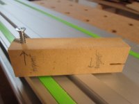
This extremely simple kerf jig provides a pretty good solution. The jig is nothing more than a block of wood with a screw in it. The screw protrudes the exact width of the router bit width.

The only difficult part is actually adjusting the screw. Just a bit of a turn in either direction will make the fit loose or tight.

Any suggestions on how to improve this would be gladly welcome.

How the jig works:

When making a dado cut with an undersized bit, you need to make two passes. The first pass will make a kerf exactly the size of the router bit. For the second pass, you need to move the router over exactly the width of the material minus the width of the bit. If your material is 19.2 mm thick, and you have a bit 12.6 mm (1/2'') in diameter, you need to move your bit over 19.2 mm - 12.6 mm, or 6.6 mm.

The jig saves you from having to calculate this number, and more importantly, move the router over exactly this distance.

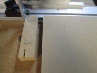
In the second picture, you see the board to be cut rests against the jig with the screw protruding. The jig rests against the fence.

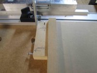
In the second cut, the board rests against a scrap piece of material the same thickness as your board going into the data. This scrap rests against the jig's non screw side, and both jig and scrap rest against the stop.

For the first cut, the jig pushes the board to the right the length of the screw. For the second, the setup pushes the board to the right the width of the scrap minus the width of the screw sticking out, or minus the width of the router bit. But this is exactly what we want for the second pass: to move the board to the right the width of the board minus the router bit.

As long as you use the same router bit, this setup will allow you to make a perfect dado in two passes, regardless of the width of your material.

The only tricky part is adjusting the screw so it protrudes exactly the width of your router bit. Bridge Tool's kerfmaker achieves this by fitting your router bit inside the jig itself. I achieve his by placing the router bit on the board and adjusting the screw until it feels flush with the edges of the router bit. I make a test cut and then adjust the screw accordingly. In order to make my dado fit more tightly, I shorten the screw. For a looser fit I lengthen it.
 

Attachments

  • kerj_jig.JPG
    kerj_jig.JPG
    154.8 KB · Views: 1,651
  • kerf_firt_cut.JPG
    kerf_firt_cut.JPG
    216.7 KB · Views: 1,577
  • kerf_second_cut_small.jpg
    kerf_second_cut_small.jpg
    204 KB · Views: 1,230
Using a screw with very fine threads would improve the fidelity, and choose a screw with a constant core diameter.

I don't get why the screw protrusion is set to the bit diameter.  I would think it would be set to the distance the workpiece needs to be moved for the 2nd pass to arrive at the correct dado width.  The process might be make 1st pass with the jig flipped around and the screw out of the way, then flip jig to add the screw protrusion distance, thus moving the workpiece over the appropriate amount, and make the 2nd pass.

Maybe an explanation as to how you are using the jig would help.

Ed
 
Pretzel Logic said:
Using a screw with very fine threads would improve the fidelity, and choose a screw with a constant core diameter.

I don't get why the screw protrusion is set to the bit diameter.  I would think it would be set to the distance the workpiece needs to be moved for the 2nd pass to arrive at the correct dado width.  The process might be make 1st pass with the jig flipped around and the screw out of the way, then flip jig to add the screw protrusion distance, thus moving the workpiece over the appropriate amount, and make the 2nd pass.

Maybe an explanation as to how you are using the jig would help.

Ed

Good suggestion. I think I need a machine screw. Or it might be better to use any screw, and once it is the perfect distance, hold the screw permanently in place with some adhesive, and always use the same jig for the same router bit. If you wanted a tighter or looser fit, you could used feeler gauges.

I added an explanation to my post.
 
Maybe use a threaded insert and if you incorporate

a digital caliper you can dial it in a little better.

[attachimg=1]
 

Attachments

  • 12J20[1].jpg
    12J20[1].jpg
    67.2 KB · Views: 8,543
waho6o9 said:
Maybe use a threaded insert and if you incorporate

a digital caliper you can dial it in a little better.

That could work. I think screws come in x threads per inch, so doing a little math, you could determine that one full turn = x distance. I find it too difficult to get an accurate measurement with calipers.

This is such a simple idea, it would be nice for a tool company to offer it. You would just need an aluminum extrusion and a knob that with an indicator on it, like with Festool's router guide.
 
Paul, got it, I didn't notice the scrap in the 3rd pic before.

You may want to change the second to last sentence in your edited post.  It should read " In order to make my dado fit more loosely, I shorten the screw".

There may be some homemade and commercial offerings out there you could use.  Try looking up micro adjuster for router table fences.  You might be able to modify and/or mount one on a base.

http://www.amazon.com/Kreg-KMS7215-Micro-Adjuster-Router-Fences/dp/B0007VYL52
 
Back
Top