DIY Fully Articulating Boom Arm you can make to use with Festool products

Status
Not open for further replies.

martin felder

Member
Joined
Dec 17, 2019
Messages
125
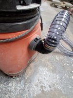
For years, I used the Festool non-articulating boom arm as the massive Festool ASA-5000 was not available in the USA and if it was, it would be a bit much for my shop.  I liked my Festool 203151 compared to no boom arm, but always thought an articulating boom arm would be better (assuming you do not need portability) for my application.  Mounted above cabinets above a workbench with the attached CT-36 below the workbench, no loss of valuable space.  Most importantly, the articulating boom arm with an 8-10 ft extended length offers functional advantages.

[attachimg=1]

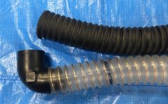
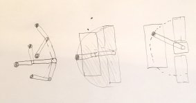
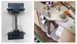
In the above picture, on the right, with a swivel non-articulating boom arm, the hose comes down along the arc as shown on the drawing on the right.  If you want to use a tool like a sander not along the arc, the hose has to be at an angle and can pull on the dust port of the tool.  If you have extra length hose to compensate, the hose can drag or lead to the tool wanting to tilt (not good when trying to keep the sander flat) etc.  With an articulating boom arm, the hose comes straight down anywhere at all points along the arc and within the arc (shaded in the center drawing).  That makes it much easier to use over a much wider area and can swivel easily out of the way.  My friend RandyC and I have been working on a DIY homemade boom arm, and here are a few pictures.

[attachimg=2]
[attachimg=3]
[attachimg=4]

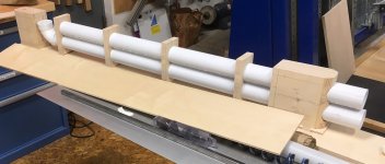
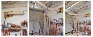
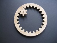
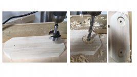
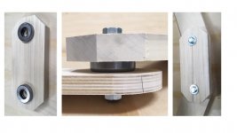
This prototype was mounted this past week.  Freely articulates, and no sag.  Just waiting on the hose.  Not expensive to build.  This involved a fair amount of drilling and cutting into aluminum.  I am working on an alternative model where I will try to make the middle section mostly out of wood using 2 inch OD angled thrust bearings and a 2 inch Forstner bit and then we can do a comparison.  It is possible that once we compare these variations, someone with the CNC and machining equipment will be willing to make for others the middle section piece for sale. 

For this DIY shop made boom arm, I hope to soon be providing detailed drawings and step-by-step pictures, and links to where you can buy all of the parts.  The goal is for you to be able to make a fully articulating 8-10 ft boom arm easily at a cost of $200 - $300.  It took a lot of time and some money working on this so that I could have an articulating boom arm myself, and so I figured you could all benefit from my experience with this project.  I have benefitted from advice over the years, and happy to give back.  To be clear, I have no financial interest in this and am not looking to sell anything or profit in any way.  I will keep you posted.


Attachments

  • Articulation.JPG
    Articulation.JPG
    246.1 KB · Views: 14,738
  • Segment.JPG
    Segment.JPG
    331.6 KB · Views: 17,964
  • components.jpg
    components.jpg
    181 KB · Views: 16,469
  • DIY boom arm.jpg
    DIY boom arm.jpg
    338 KB · Views: 15,761
Are those gears in the knuckle on the top or bottom? If they are on the bottom they will collect sawdust faster than if up top.

Or you could enclose that whole section with a pleated boot or sock. Just need a piece of sturdy cloth with Velcro strips to fasten it to itself after you wrap it around. Or use magnets sewn into the corners and along the edges.
 
In these photos, they are on the bottom but could just as easily be located on top.  Thank you for the suggestion.  As for your other suggestion, certainly that is an option, especially if the material can easily stretch.  For the flex hose  for that middle section, I have 2 on order.  1 will compress from 12-6 inches, and a slightly more expensive option will compress 12 to 2 inches.  Whatever is in that section has to be able to stretch-compress. to allow full articulation without resistance.

I am very much an amateur when working on these things, and my friend RandyC who deserves a lot of credit for his contribution to this project, also has no experience designing and making articulating boom arms, and so I am always looking for ways to improve it.

Another option is to not have the bottom pipe for the power cord cord, and drill a number of round holes (eg large forstner bit) along the sides of each arms.  The holes would decrease the weigh and facilitate the threading of the power cord within each segment of the boom arm in the absence of the bottom pipe.  That would save a bit of money on the pipe also, but not look quite as sleek.  Trade off.
 
If the hardware and mechanical parts (gear etc.) are available for sale, I 'd be interested even though I have no immediate needs for any boom arm given my shop limitations.

I'm a woodworker and those plywood builds would be a piece of cake to me. I don't even need to run two tubes, just one for the cord and hose together, further reducing the weight or stress on the gears/ bracket, etc. perhaps.

I'm totally not concerned about dust contamination of the gear or whatnot as I can clean up any dust there every time I clean my dust collector and DDs (usually once every two months or three).

Thanks for sharing. I'll monitor this thread for any new updates.
 
This boom arm is hanging up in my shop as of right now.  My concern was sagging of the outer arm.  There is no sag at all now that it's mounted.  It works perfectly.  I'm just waiting for the hose to connect in the middle.  I'm going to run an electrical cord, and air line and the Festool power cord thru the lower pipe and tie onto the vacuum hose.  It will really help with keeping my floor free of cords and hoses and whatnot's..
There's a few improvements I will be working on to make it even better..
 
ChuckM,  what was posted was made in a woodshop using a Kapex and a Powermatic woodworking drill press.  All components were commercially available at the Home Depot or online, and once I experiment with a modification next week to see if certain things in aluminum can be made more easily with wood, RandyC and/or I will post links to where everything can be ordered as far as parts like the gear. 

The goal is for it to be fully functional, well-built and durable, easy and not too time consuming to make with commercially available parts in a woodshop, and inexpensive. 
 
Did you consider making the gears from wood? Matthias Wandel has a nice online gear generator app on his web site, or did the last time I visited. You can use it to create templates you can use to make your own gears in any size with as many or as few teeth as you desire (within reason).

Since you are using a box beam type of construction for the arm segments you don't need any structural rigidity in the tubing. There are lighter weight tubes available but not sure if the reduced weight is enough to warrant using them.

Since I live in a rural area every time I go to the dump I watch for someone tossing out an old kids swing set. Some of the pieces will even have well formed bends that could suit dust collection projects. I think that steel tubing used in the construction of those has multiple uses when repurposed. One I have been wanting to build is an overarm dust collection for my table saw.
 
The PVC pipes are central vacuum pipes and are extremely light in weight.  We want the overall boom arm to be as light as possible, but yet be just as functional as a commercially available boom arm. the spacers inside the arm where the pipes pass thru are for not only support, but to keep the pipes from rattling and to give the 1/4" outer skin something to attach onto.
 
Bob,
https://woodgears.ca/gear/howto.html

I wanted something that could be made easily in very little time using commercially available parts.  With the gear I purchased online, you drill a hole in the top and bottom plates, index 1 of the gears with a bolt, set the 2nd gear so it meshes, and that tells you where the second hole should be, and you drill there, and you got the right spacing.  When the gears are secured to the arms of the boom arm, the spacing will be correct and it will work.  I would have preferred gears with less and bigger teeth, but bottom line is that the ones I found work.  On the 2 inch OD pipe that is much lighter than PVC, the idea was smooth tubing for the dust collection that was as light as possible to reduce weight.  It just has to be a conduit for dust as it is not what gives the arms strength-rigidity.

Once I get the hose and second set of gears that are being shipped and make a variation of the middle section using wood instead of aluminum in the top-bottom plates and a different bearing approach, I will post these details so anyone can make one easily.  That is the goal.  Of course, I imagine others will have ideas for options that will allow it to be made better or at even less cost.  For gears out of wood, that saves money, but takes a lot more time.  Painting it would make it look nicer than leaving it unfinished, but that takes time.  One could use a bottom pipe or not. The aluminum middle section is strong and looks cool (a lot of credit to Randy) but if I can have the same functionality with some wood substitutions, that would save a bit of money and decrease construction time.

What would just need to be common in all variations is for the boom arm to properly swivel at the mounting bracket, swivel 180 degrees easily in each direction at the articulation, and not twist or sag.  Once I post the parts list and assembly pictures, I am looking forward to see what you all have to say, especially since I am just an average hobby woodworker, and I know many of you are very innovative with way more experience. 
 
Getting more excited about this boom arm as more details are coming out. For myself, I'd definitely take the easy way out if I'm to build one, that's using commercially available parts and materials. I kinda like a more turn-key approach for this particular project.

I may build one (probably for a 7 to 8 feet version), and put it aside until I move to a place where I have a higher shop ceiling to use it. Even if I don't get to use it for any reason in the future, the estimated cost seems to be something I can write off without too much agony. :P

For those interested in making or planning to make their own gears, make sure you choose the right wood to allow for wood movement, wear (broken teeth can be fixed but often fail again in time),  etc. I have made a good share of gear parts in the past, and precision is critical for smooth movements and in some cases, long-term use.
 

Attachments

  • IMG_9390.jpg
    IMG_9390.jpg
    516.9 KB · Views: 590
Bob D. said:
Did you consider making the gears from wood? Matthias Wandel has a nice online gear generator app on his web site, or did the last time I visited. You can use it to create templates you can use to make your own gears in any size with as many or as few teeth as you desire (within reason).

Since you are using a box beam type of construction for the arm segments you don't need any structural rigidity in the tubing. There are lighter weight tubes available but not sure if the reduced weight is enough to warrant using them.

Since I live in a rural area every time I go to the dump I watch for someone tossing out an old kids swing set. Some of the pieces will even have well formed bends that could suit dust collection projects. I think that steel tubing used in the construction of those has multiple uses when repurposed. One I have been wanting to build is an overarm dust collection for my table saw.

Bob, as a side note regarding table saw dust collection, have you seen this recent video by Mike Farrington?=625s
 
I mentioned I am waiting on another gear to try a different approach to the bearing of the swivel articulation section that would make construction easier, this is a preview (gear omitted).  In the previously posted pictures with the mid section made of aluminum, Randy seated bearings in the top and bottom aluminum plates.  My thought is to have wider bearings with a larger surface contact area sandwiched between the plates and the arms.  I am really not sure if this will work as well or is better or not than what we know works in the posted example.  When I get the gearsI , I will see.
https://www.amazon.com/dp/B07RV1P6CD?psc=1&ref=ppx_pop_dt_b_asin_title

The above are tapered thrust roller bearings with an OD of 2 inches.  You can get 2 for $12.19 and you need 4. 

[attachimg=1]

In the above picture, I am using a 2 inch OD Forstner bit to drill shallow holes in the top plate.  That can be duplicated on the bottom plate and I was thinking 1 inch or 1 1/4 thick maple (or oak would do).  Then, bore the smaller hole for the bolt using the center marking to insure the smaller through hole is dead center (or keep the wood clamped to the drill press table as you change from Forstner to the smaller bit).

[attachimg=2]

When the bearings are inserted into the shallow hole, the ID of the bearing does not have to be around the size of the bolt. It just has to be no smaller.  Then, with holes for the bolt drilled into the arms, you assemble with washers on the top and bottom, and a lock nut.
Very fast and simple and inexpensive.  One option would be to make shallow wider holes in both the top-bottom plates or arms.  What would make it sag would be the nut coming loose or the wood bending or the bearing failing but one does not have to worry about seating a bearing within metal precisely and I think the wider surface area of this bearing is an advantage.

These are all guesses as I am very much learning as I am going.  I know this is easier than dealing with aluminum and I just want to find out if it will work as well or not.  Doing it this way takes 15 minutes at most and this is the most critical part of the entire project, but it does not matter if it is easy, inexpensive and fast if it sags. 


Attachments

  • Forstner hole.jpg
    Forstner hole.jpg
    297.5 KB · Views: 13,900
  • Bearing 1.jpg
    Bearing 1.jpg
    272.5 KB · Views: 14,237
FYI, there are 2 people I know of that expressed an interest in making the middle section for now as a one-time project with CNC and metal working machinery and to make it available to others at a very reasonable price as a "one-time tool", like Woodpeckers! 

This entire project was made in a woodshop, but for those who want the most "turnkey" DIY articulating boom arm, it would be by being able to buy the articulating section, and this may be something to consider.  If you are at all interested, with the understanding it may depend on price, please send me a PM as I can gauge the level of interest and forward the information.

To again be clear, I have no financial interest in this directly or indirectly.  I am just mentioning that this may be an option if there is interest since a couple of people may plan to make this middle section. 
 
Martin, Randy

Nice work guys! I love to see shop-built stuff on this website.  Like Bob, I would also like to build something like this for the DC over the blade of my table saw.

I'll continue to follow the details as you work on this.
 
Darn you [member=71926]martin felder[/member] for that link to the bearings. Now I've gone and bought a couple sets. :-)
 
Hey there, neat project Martin & Randy, thanks for sharing!

Question:  I hate to be a dope, but why are the gears needed?
 
Straightlines said:
Question:  I hate to be a dope, but why are the gears needed?
So it bends symmetrically. There are 3 sections (note short middle section). Without gears it may end up in a Z-shape, will still work but may kink the hose. Gears could be substituted with rubber tires, but those will shift over time.
 
I am still waiting on the additional gears so I can see if I can make a middle articulating section more easily and even more inexpensively using wood instead of aluminum for the top and bottom plates.

For an articulating boom arm to work properly, one component is the mounting bracket.  That needs to just be a vertical rod connected to the first arm of the boom arm so the boom arm can swivel at a pivot point.  A hinge can do this, but it has to support the weight of the boom arm.

What was effective and what was used to make the pivot point mounting bracket in the pictured boom arm are the products below:
https://www.grainger.com/product/DAYTON-2-Bolt-Flange-Bearing-with-3FCN4https://www.speedymetals.com/pc-3951-8210-3-x-3-x-14-angle-a-36-1020-hot-rolled-steel.aspx

If anyone has a suggestion for a better option, please let me know.

As for the 2 arms that carry the dust hose-pipe and electrical cord(s) and perhaps an air hose line, the pipe used was previously posted and within each arm can be just pipe for the vacuum or 2 pipes with 1 for the vacuum and the other for the electrical cord(s).  Detailed plans to follow, but there are some options.

Connecting these 2 pipes in the middle is 2 inch ID hose to fit outside the 2 inch OD pipe (with hose clamps).  I just got 2 different hoses from Air Handling systems (see picture).  The more clear one is extremely flexible and is the perfect choice.  The black one is more stiff but is available at shorter lengths and so I want to see if that will work well because if it does that will reduce cost. 

I was wondering how to connect the boom arm to the Festool vac (eg. CT-36).  I had a hard time finding the answer.  What fits in the vac is something that is around 58mm OD which is around  2.25 inches OD.  What I did was get this:
https://www.oneida-air.com/2-5-inch-static-conductive-vacuum-hose-elbow

It is from Oneida and only costs $10.85.  Notice it says 2.5 inch hose elbow. Well, if you look at the specifications, it says one end is 2.25 OD, perfect for plugging into the Festool Vac, and the other end is 2 inch OD, perfect for standard 2 inch ID hose!

I got it and it worked!  Randy used it on his Fein Vacuum and that worked also (see picture).  That solved the issue of making sure the boom arm would work with Festool vacs.  Just that elbow to flex hose to boom arm.  I was thinking maybe a short piece of flex at the boom arm and vac ends and then maybe some 2 inch pipe in between going up the wall to have less flex hose and a nice way to clamp the pipe to the back wall.  Hmm.

Anyhow, so far, the boom arm that was mounted in Randy's shop has held up very well, and will be connected within 24 hours now that the hose and elbow parts have arrived.  Seems like we were successful in our goal and the followup will be with more specific details. 

In anyone has any constructive criticisms and suggestions for improvement, please let me know. 


Attachments

  • 20200529_141653.jpg
    20200529_141653.jpg
    1 MB · Views: 938
  • IMG_4855.JPG
    IMG_4855.JPG
    808.2 KB · Views: 812
"If anyone has a suggestion for a better option, please let me know."

Couldn't you use the same components you did for the knuckle in the middle of the arm?

A pair of those bearings with a 1/2" all-thread rod.

For additional support with either method a 1/4" cable stay run from an eyebolt centered over the wall hinge and up a couple feet out to the end of the first segment of the arm. Might create some clearance problems in certain situations but adds a lot of support at low cost.
 
Status
Not open for further replies.
Back
Top