DIY Fully Articulating Boom Arm you can make to use with Festool products

Status
Not open for further replies.
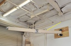
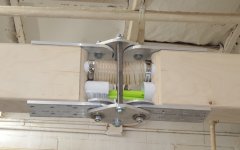
Thanks for the suggestions.  On the eyebolt-cable, if I understand correctly, it would be like as shown by the yellow line in this picture.

[attachimg=1]

My take on that is that it certainly would add support to the area of the mounting bracket and the first arm at a very low cost and would take 5-10 minutes to install.  That would be an option I will mention when I post detailed plans.  More support is a good thing.

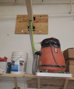
A boom arm can be mounted at any height, but my personal opinion is that the bottom of the boom arm should be around 6ft 8 inches to 7 ft above the floor so (unless you are super tall) so it is well above your head but you can reach up easily to move it without only moving it using the hose coming down.  That means the top of the mounting bracket would be getting close to 8 from the floor.  Adding this support is only possible for those with very high ceilings.  Fortunately, the boom arm we made does not seem to need that additional support to function nicely without sagging and that creates more universal appeal.  Hopefully that will be the case with the even easier to make version I will be working on when I get the new gear.

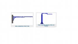
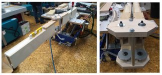
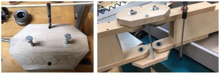
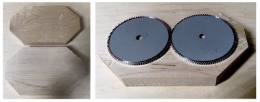
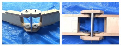
On the other suggestion, not exactly picturing what is being suggested.  If it is a different option for the mounting bracket, any more details would be helpful.  For what is being used now, we have 2 commercially available parts from Grainger bolted to an angle piece that mounts to the wall with a rod going vertically.  Thanks.
 

Attachments

  • Screw eye.jpg
    Screw eye.jpg
    1.5 MB · Views: 19,323
I think if I was building one(or when) . I would make the wall mount plate a lot longer, say 36 inchs  and make the gusset piece on the first arm on the underside . that should add a lot of strength to hold it up and shouldn't be in the way too much
 
It is interesting to see the variations in how articulating jib cranes are attached at the mounting plate - initial pivot point.
https://www.ergonomicpartners.com/articulated-jib-cranes#ArticulatingJibsFS

If I understand, you are suggesting something more like the picture on the left below

[attachimg=1]

One thing nice about the mounting bracket in the previously posted picture is that you have the ability to have a longer vertical distance at the pivot point just by using a longer 3/4 inch diameter rod.  The boom arm as is seems to be doing just fine without further support but certainly nothing wrong with more support.  For me, it would be problematic since right below where I plan to mount my boom arm, there are storage cabinets.  However, I do have room above should I want added support using the eye bolt idea. 

One thing that I think helps this boom arm be OK without modification is that it is light.  If only the 1 pipe were used (for vacuum hose), it would be even lighter. 

Thanks!
 

Attachments

  • boom arm lifts.jpg
    boom arm lifts.jpg
    71.9 KB · Views: 13,452
that's exactly what I mean.
if you have the room above then  it is way better to have it up out of the way
 
Once I check to see how the alternative mid section swivel option will work out, and then post a step-by-step guide to making one, Randy and I will be sure to indicate how certain things can be modified as options for those with certain preferences.  Another example of that is seen in this picture

[attachimg=1]
The very flexible vacuum hose is seen connecting the 2 pieces of light weigh 2 inch OD pipe (available at Home Depot).  Here you see the pipe below it, but no hose yet installed.  That bottom pipe is to thread the power cord (or 2 cords with 1 plug-it and the other standard extension cord).  The pipe and the bottom hose can house the cord.  However, another option is to have omit the bottom pipe and hose and have the cord travel within the boom arm where it will travel under the top hose.  Another option is to have a small flex hose connected to a very short piece of pipe on each arm (then travel inside the arm) so the cord is covered and protected at the point of articulation, but you save a few dollars on the pipe and a small amount of weight.
 

Attachments

  • Boom Arm with hose.jpg
    Boom Arm with hose.jpg
    543.8 KB · Views: 16,602
Considering it only needs to support some thin wall pvc and vac hose wouldn't something like this be simpler?

oVmw7J.jpg
 
https://www.festoolownersgroup.com/festool-jigs-tool-enhancements/another-homemade-boom-arm-63015/

Nice drawing!  For sure that would be more simple and is similar to what was recently posted in a separate thread in response to this thread.  With that design, the maker indicated adding a second articulation was what allowed it to best function.

Interesting that before I pursued upgrading to an articulated boom arm, I could not find one example of a shop made DIY option, and so we incorporated some of the features of the original Festool ASA-5000..

Nice for people to now be aware of options to pick what is best for them, especially if those other very inexpensive DIY options have the same functionality of allowing 8-10 ft extended lengths, no sag, and full articulation.  Are you going to make one like that?

 
It's my homemade boom arm that Martin has linked to.

Regarding the plan that Banana has posted my very first attempt was similar to that, I just used single pieces of 18 mm birch ply for the arms. I found that in use the triangular piece of ply twisted under the weight once the two arms were not in line causing the the arm to sag. I remade it using a torsion box style, some 2" x 1" with a 12 mm birch ply skin over which solved it.
 
"On the eyebolt-cable, if I understand correctly, it would be like as shown by the yellow line in this picture."

Yes, your sketch with the cable stay added shows what I am suggesting.
 
Now I understand.  While I appreciated the engineering & rock solidness of Martins box design (hadn’t seen other thread yet) I just couldn’t see past the light weight it had to carry.

The Doug S version has many solutions to issues I hadn’t considered. 

Learning about the ply twist regarding the cheap’n’cheerful mockup I posted (limiting it to only mounting ‘nose down’ as shown),  I wonder if adding significant and equal ballast, on both sides, near the tip of the nose of triangular main arm would stop this?

The only other down'n'dirty approach I’d entertain would be a single longer main arm (of any design) with an under mount track for one or two trolley wheels.  Of course now you get hose draping and hang yourself each time you walk straight into it.  [wink]
 
Boom Arm Version 1 in Randy's shop

[attachimg=1][attachimg=2][attachimg=3][attachimg=4]

That boom arm had a flexible extension cord and air hose, with the air hose now replaced by a plug it.  No sag.  Moves well.  Seems to be functioning perfectly.  However, version 2 will have a few minor changes with Randy thinking of ways to make beneficial tweaks.  For example 1 inch more space on each arm to allow a slightly longer flex hose which may allow cheaper hose to work as well, a bit more distance between the upper and lower pipes to allow more room for the hose and hose clamps etc. 

I now have all of the parts needed to try seeing if I can substitute the aluminum top and bottom plates and use 1 inch thick maple along with the wider thrust bearings to see if we can have the same functionality with easier-faster construction.

Seems to not be a question of it we can make the boom arm or not and have it work well, but if we can make a few changes to make it better, easier to make, and for even less cost.  Plans to follow after that.
 

Attachments

  • Hose coming down.jpg
    Hose coming down.jpg
    549.8 KB · Views: 24,703
  • Center flex.jpg
    Center flex.jpg
    496.7 KB · Views: 25,977
  • Center.jpg
    Center.jpg
    343 KB · Views: 24,209
  • Mount.jpg
    Mount.jpg
    740.8 KB · Views: 23,655
This looks great!  Looking forward to seeing the plans!!!

Thanks so much!
 
Looks pretty good. Please also provide plywood thickness and tube size if possible fro reference.
 
OK.  Made the articulating section out of wood.  Took very little time.  It ended up looking like this and worked perfectly.
[attachimg=1]
For this, I had the 2 gears and 2 inch OD angled thrust bearings x 4 (links previously posted), two 3/8 hex bolts that were 12 inches long (Ace Hardware), some M10 hex bolts, some fender washers, and some lock nuts for the M10 hex, a couple of aluminum tubes (any narrow pipe will do), some 1 inch maple and some 3/4 plywood. 

So.... first thing was to cut some 1 inch maple - 5.5 x 9 inches x 2 pieces and cut the corners at 45 degrees.  That has nothing do to with function but looks nicer.  If you want it to look even nicer you would do a 3/16 or 1/4 roundover and sand.  I made no effort to make them perfectly identical.  As you can see, if you were to put the gears on top, they would fit
[attachimg=2]
With the gears sitting on top of 1 of the maple pieces mark the center, and drill a hole around 1/4 inch deep with a 2 inch Forstner bit.
[attachimg=3]
Then, keeping the wood clamped to the drill press table, change the bit to a 25/64 or 13/32 bit and drill the hole all the way through.  The center indentation from the Forstner bit is a nice way to know the center also.  This will allow a 10mm bolt to go through.  25/64 is adequate, but you can go 13/32 if too snug. 
[attachimg=4]
This is key.  After you drill the first hole, Take one of the gears and place it as shown and use a drill bit or a 10mm bolt to keep it in place.  Then place the other gear next to is so it meshes.  Then, use a 24/64 or 13/32 brad point bit and insert it through the center bore hole in the gear, and tap it to mark the center.  Then drill the 1/4 inch hole with the Forstner, then drill the other hole through in the center.  If you were to then place bolts through both holes, the gears will mech.  Essentially, you are using the gears to mark the distance between them rather than a ruler. 
[attachimg=5]
Now, on the left you see the 2 Forstner holes and the 10mm or so holes in the middle which are the prefect spacing for the gears to mesh, but we need to duplicate that on the other piece.  So, we put 1 on top of the other, and then use the brad point bit to mark the center.  On the picture on the right, the black arrows show the indentations.  For that piece, you drill the Forstner 2 inch diameter holes and the center holes.
[attachimg=6]
Now, take 4 pieces of 1 inch thick maple 14 inches long and 3 inches wide and mark the center 1 1/2 inches before the end for each piece.  Drill the hole in that marking with the 25/64 or 13/32 bit and round the corners.  The center marking does not have to be perfect.
[attachimg=7]
Now, drill 2 holes for the 3/8 long bolts as shown. Once you do that, then pub the 2 pieces on top of each other and do that same tap with the brad point to mark the corresponding location on the other piece and drill.  Then you assemble as shown on the right.  For this prototype, I used some 3/4 plywood for the arms 6 inches tall and 3 inches wide.  The 4 pieces of 1 inch thick maple were screwed to the arms.  For the undersurface of the top 2 of these, I drilled a hole in the gear and screwed it to the maple with a bolt running through so the gears would be centered. 

For the assembly, on the top, you have the top plate and the bottom plate with the 2 inch OD bearings seated into the wood (courtesy of the hole with the Forstner bit).  Under these plates, you have the extension pieces of maple connected to the boom arms with the gears under the top extensions.  Through the holes you have the 10mm bolts and washers and lock nuts.
[attachimg=8]
I clamped it to the bench and tested it.  Worked perfectly.  I added 20 lb barbell plates to the end.  No deflection.  I lifted it up 7 ft and dropped it on the floor, no damage.  I swiveled it side to side and it never moved on its own but no resistance either.  No wobble or sag.

So far so good.  Again, this is just a preliminary report. I will provide way better detailed plans with more info on exactly how to attach the gears and assemble.  I think the aluminum is the best, but for those who want something more simple, and even less expensive, this seems to be an option that is super easy to make.
 

Attachments

  • 8 arm.jpg
    8 arm.jpg
    309.8 KB · Views: 22,060
  • 7 arm.jpg
    7 arm.jpg
    263.4 KB · Views: 22,042
  • 6 arm.jpg
    6 arm.jpg
    156 KB · Views: 21,687
  • 5 arm.jpg
    5 arm.jpg
    182.4 KB · Views: 21,822
  • 4 arm.jpg
    4 arm.jpg
    241.8 KB · Views: 21,967
  • 3 arm.jpg
    3 arm.jpg
    200.6 KB · Views: 22,078
  • 2 arm.jpg
    2 arm.jpg
    318.7 KB · Views: 22,201
  • 1 arm.jpg
    1 arm.jpg
    321.6 KB · Views: 22,679
Oh... a couple of people are interested in making a YouTube video going over the instructions step-by-step. 
 
If you want to simplify the design, you can replace gears with straps or cables as shown below (red). Straps attached only at the ends and transition from one curve to another. This principle is widely used for symmetric rotation from children's toys (Jacob's ladder) to industry.

[attachimg=1]

[attachimg=2]
 

Attachments

  • joint1.JPG
    joint1.JPG
    53.7 KB · Views: 21,639
  • joint2.JPG
    joint2.JPG
    39.8 KB · Views: 21,434
Thanks Svar,

If you have a link to a particular product for straps you recommend as a nice durable option, I can try it.  That would be as easy as unscrewing and removing the gears and adding the straps to see how well it works.  As far as design, I believe it is simple very simple to build with clear detailed instructions and a materials list now that the bugs are worked out.  The gears are just meshed together, and that guides where you drill the holes on the top and bottom plates. That correct spacing is all that is needed to insure the gears work when secured to the boom arm and the center section is assembled.  However, the if straps have identical functionality, and are less expensive, that sounds good!  I already have the gears and it already works, but as I said, I want to see just how easily it can be made at a low cost without compromising functionality and durability.  Therefore, happy to experiment so others can save $ if it works.
 
Perhaps a discarded fan belt picked up from a repair shop would suffice to test with?  The composition / lack of stretch / strength / ability to drill through for fastening etc. should exhibit the properties of a similar premium product. 
 
A great build and good thinking but I am curious why the gears are used? Also did you consider Timken Taper bearings which are adiustable to some extent and having long rollers give more bearing surface area. The one big factor that may be a problem for some is they are not sealed at all. I have built one boom and it was a total failure though it was one piece with no articulation but you have given me ideas on version two. 
 
The gears prevent the extended boom arm from over traveling and keeps them parallel to each other when rotating.
 
Status
Not open for further replies.
Back
Top